Power unit and method

a power unit and power technology, applied in mechanical equipment, transportation and packaging, gearing, etc., can solve the problems of reducing the life of the control motor, the overall and the transmission of torque, so as to increase the efficiency of the power unit and prevent the transmission of torque from the control gear to the rotor of the control

Pending Publication Date: 2022-08-18
REVONTE OY
View PDF1 Cites 1 Cited by
  • Summary
  • Abstract
  • Description
  • Claims
  • Application Information

AI Technical Summary

Benefits of technology

[0046]An advantage of the invention is that that transmission of torque from the control gear to the rotor of the control is prevented at the low transmission ratio of the main epicyclic gear set when the control gear would otherwise rotate in the second rotation direction opposite the first rotation direction. Further, the rotation of the control gear is not transmitted to the rotor of the control motor when the rotation speed of the control is zero or negative in relation to the first rotation direction. Therefore, rotation of the rotor of the control motor in the second rotation direction is prevented. This, prevents the control motor from hating excessively and further the efficiency of the power unit is increased.
is that that transmission of torque from the control gear to the rotor of the control is prevented at the low transmission ratio of the main epicyclic gear set when the control gear would otherwise rotate in the second rotation direction opposite the first rotation direction. Further, the rotation of the control gear is not transmitted to the rotor of the control motor when the rotation speed of the control is zero or negative in relation to the first rotation direction. Therefore, rotation of the rotor of the control motor in the second rotation direction is prevented. This, prevents the control motor from hating excessively and further the efficiency of the power unit is increased.

Problems solved by technology

One of the problems associated with the prior art is that is that at lower transmission ratios the rotation direction of the control gear may change to opposite to the first rotation direction, meaning to a second rotation direction.
However, the problem with changed rotation direction of the control gear is that the opposite, or second, rotation direction is transmitted also to the rotor of the control motor.
This further causes that the torque is not transmitted from the control motor to the control gear, but from the control gear to the control motor.
Thus, the control motor may heat up decreasing the life time of the control motor and also the overall efficiency of the power unit.

Method used


Image

  • Power unit and method
  • Power unit and method
  • Power unit and method

Examples


Embodiment Construction

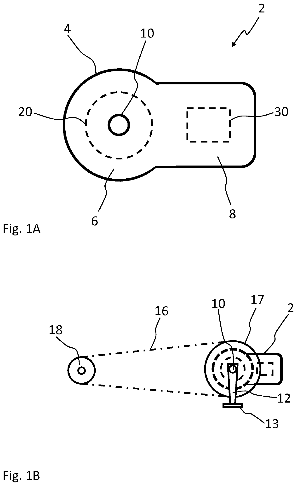
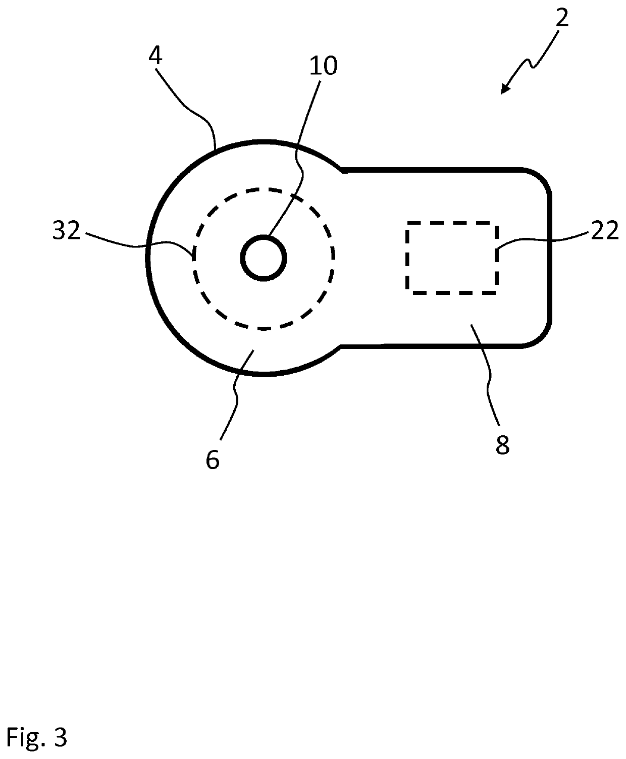
[0053]FIG. 1A shows schematically a power unit 2 for a pedal vehicle. The power unit 2 comprises a housing 4. The power unit 2 further comprises hub 6 or hub part to be arranged around a pedal shaft 10 of the pedal vehicle. The power unit 2 also comprises an arm 8 or arm part extending from the hub 6. The housing 4 forms both the hub 6 and the arm 8, and encloses the components of the power unit 2. The power unit 2 comprises a hub motor 20 arranged to the hub 6 and in connection with the pedal shaft 10 inside the housing 4. The power unit also comprises an arm motor 30 arranged to the arm 8 and inside the housing 4.

[0054]The housing 4 represents also body of the power unit 2.

[0055]The power unit 2 comprises two motors, a control motor arranged to adjust transmission ratio of the power unit 2 and an assist motor arranged to assist pedalling of the pedal vehicle. The control motor may be a hub motor or an arm motor, and the assist motor may be an arm motor or a hub motor, respectively...


PUM


Abstract

A power unit for a pedal vehicle includes a pedal shaft, an output shaft arranged to transfer torque to a vehicle wheel, a main epicyclic gear set arranged to control transmission ratio between the pedal shaft and the output shaft, an assist motor connected to an assist gear of the main epicyclic gear set, and a control motor connected to a control gear of the main epicyclic gear set. The control motor and the control gear form a control assembly of the power unit. The power unit includes a one-way clutch provided to the control assembly of the power unit and arranged to transmit rotation in only a first rotation direction.

Description

FIELD OF THE INVENTION[0001]The present invention relates to a power unit for a pedal vehicle and more particularly to a power unit according to preamble of claim 1. The present invention further relates to a method for operating a power unit and more particularly to a method according preamble of claim 10.BACKGROUND OF THE INVENTION[0002]In the prior art, it is known that utilize two separate motors in an electrical pedal vehicle. The motor unit of a pedal vehicle comprises a pedal shaft, chainwheel arranged to transfer torque to a vehicle wheel and a main epicyclic gear set arranged to control transmission ratio between the pedal shaft and the chainwheel. The power unit comprises an assist motor connected to an assist gear of the main epicyclic gear set and arranged to transmit torque to the assist gear. The power unit further comprises a control motor connected to a control gear of the main epicyclic gear set and arranged to transfer torque to the control gear. Accordingly, the a...

Claims


Application Information

Patent Timeline
Patent Type & Authority Applications(United States)
IPC IPC(8): B62M6/45B62M6/55B62M11/14F16H3/72F16D41/24F16D28/00
CPCB62M6/45B62M6/55B62M11/145F16H1/28F16D41/24F16D28/00F16H3/72F16H3/724F16D41/26F16H3/727
Inventor PELTOLA, IIRO
Owner REVONTE OY
Why Eureka
Try Eureka