Component mounting method and component mounter

Active Publication Date: 2013-03-07
PANASONIC CORP
View PDF2 Cites 3 Cited by
  • Summary
  • Abstract
  • Description
  • Claims
  • Application Information

AI Technical Summary

Benefits of technology

The invention allows for accurate mounting of small components without causing uneven loads or defects during placement. This minimizes the likelihood of defects and improves the overall quality of the assembly.

Problems solved by technology

This makes it difficult to pick up and hold-miniature components well with nozzles in some cases, since miniature components (miniature chip components in size of 1005, 0603, and 0402, for example) are unevenly disposed in the cavities due to variation in dimensional tolerance of the cavities and the components.
Such difficulties include failing to hold the component and holding the component at a tilt.

Method used


Image

  • Component mounting method and component mounter
  • Component mounting method and component mounter
  • Component mounting method and component mounter

Examples


Embodiment Construction

[0031]The following describes an embodiment of the component mounter according to the present invention and an embodiment of the component mounting method implemented with the component mounter.

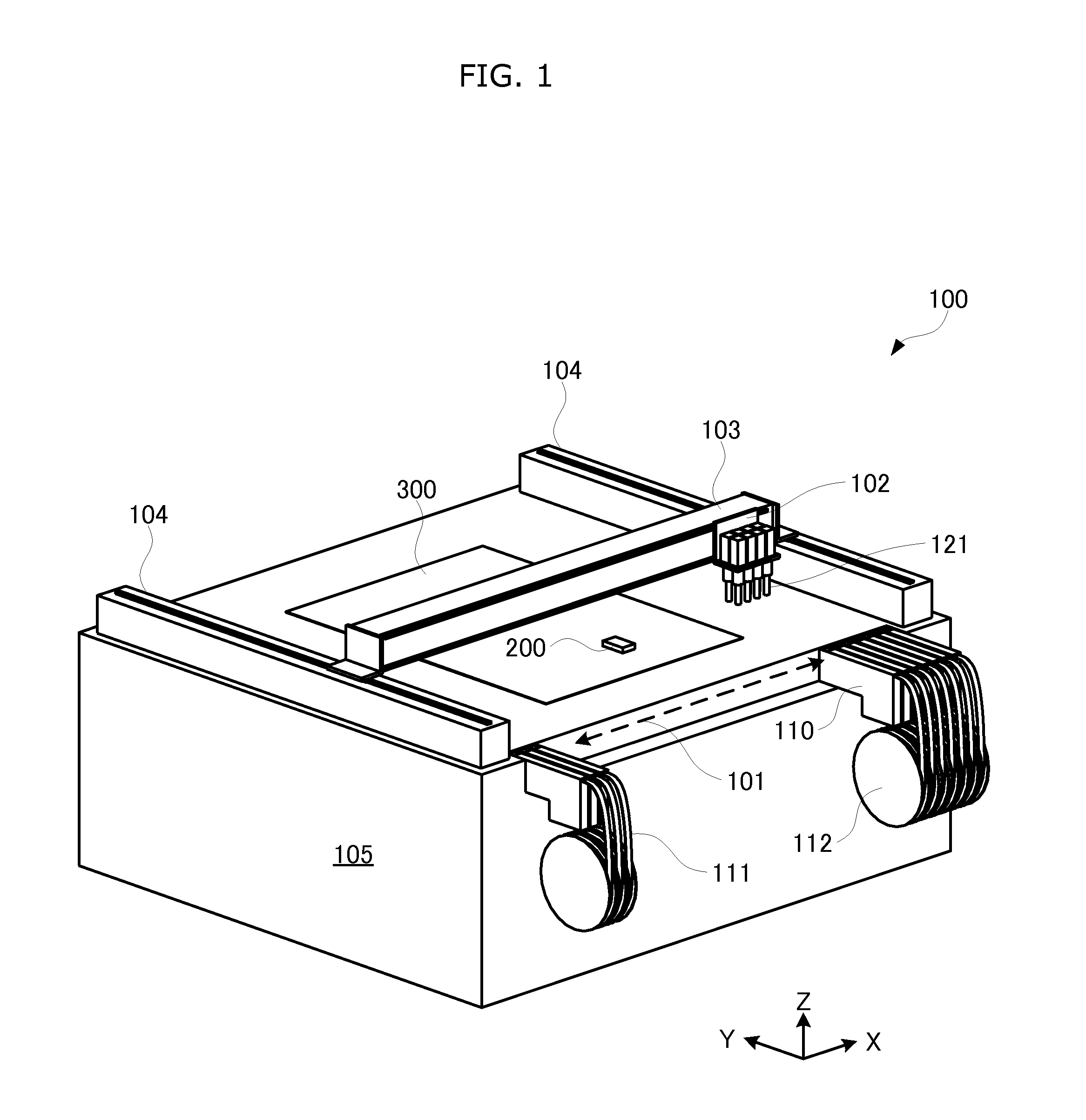
[0032]FIG. 1 is the perspective view which shows the component mounter schematically.

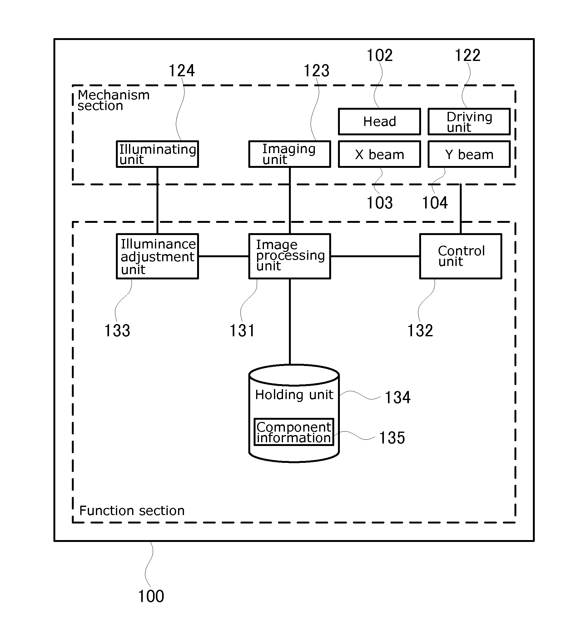
[0033]As shown in FIG. 1, a component mounter 100 is a device which mounts a component 200 onto a substrate 300 by picking up and holding the component 200 fed to the component feeding unit 101 and placing the picked-up component 200 onto the substrate 300, the mounter including: a head 102 which is reciprocatable in an X-axis direction; an X beam 103 which guides the head 102 in the X-axis direction; a Y beam 104 which guides the X beam 103 in an Y-axis direction; and a base 105 which is a basis of the component mounter 100.

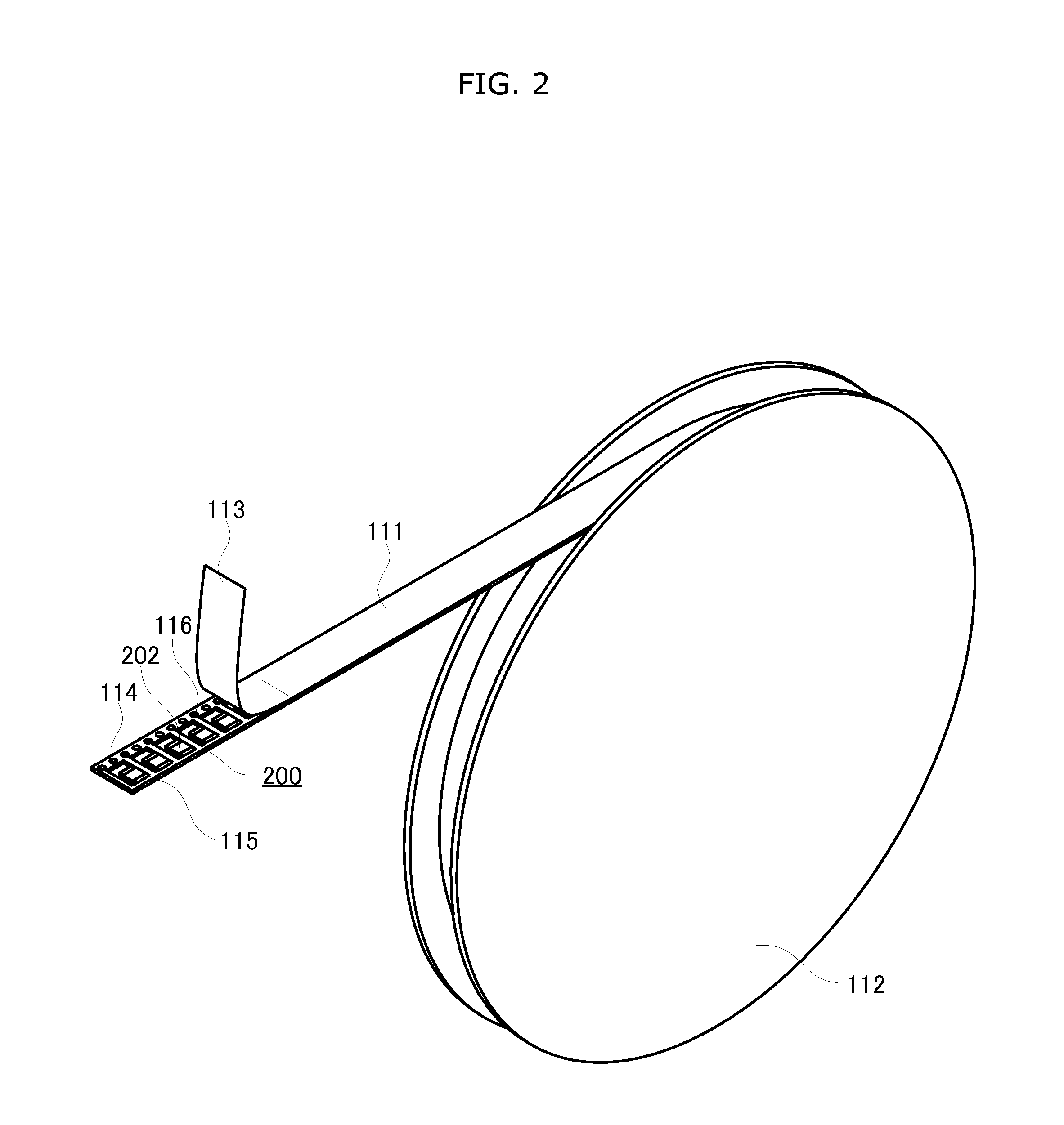
[0034]A plurality of tape feeders 110 are arranged at the component feeding unit 101. Each of the tape feeders 110 is attached to the component mounter 100 in a detachable manner. The tap...


PUM


Abstract

A component mounting method includes: identifying, by image processing, a dark color region from image data obtained by imaging a two-dimensional region including a pickup face of a component to be picked up; deriving position data indicating a position of the identified dark color region; and deriving, based on the derived position data, a pickup position indicating a position at which a nozzle picks up the component. The imaging is performed by an imaging unit, and the dark color region indicates a dark color portion between electrodes of the component.

Description

TECHNICAL FIELD[0001]The present invention relates to: a component mounter which mounts a component onto a substrate by picking up and holding the component from a component feeding unit, conveying the held component above the substrate, and placing the component onto the substrate; and a component mounting method implemented with the component mounter, and particularly relates to: a component mounter which mounts a miniature component including an electrode at both ends; and a component mounting method implemented with the component mounter.BACKGROUND ART[0002]Conventionally, a component mounter is available which attaches a component onto a substrate by picking up and holding with a nozzle the component fed to a component feeding unit, conveying the component above the substrate, and putting the component down. Components which are relatively small among the components fed to the component mounter are fed in a state being held in an array in long tape called carrier tape. The carr...

Claims


Application Information

Patent Timeline
IPC IPC(8): G06K9/00H04N7/18
CPCH05K13/0452H05K13/0413H05K13/0417H05K13/0812H05K13/0419
Inventor IKEDA, MASANORITOMOMATSU, MICHINORIFURUICHI, SATOSHITANIGUCHI, MASAHIRO
Owner PANASONIC CORP
Why Eureka
Try Eureka