Arc welding control method

Active Publication Date: 2015-04-09
PANASONIC INTELLECTUAL PROPERTY MANAGEMENT CO LTD
View PDF11 Cites 14 Cited by
  • Summary
  • Abstract
  • Description
  • Claims
  • Application Information

AI Technical Summary

Benefits of technology

[0018]The method of the present invention, as described above, minimizes defects, such as a pit and a blowh

Problems solved by technology

The reason is that steeply increased welding current at arc regeneration wobbles the molten pool and causes unstable movement of a droplet on the tip of the wire.
The phenomenon easily causes a feeble short circuit between the wire and the base material, increasing spatters.
Further, the aforementioned current control provides an arc length immediately after arc regeneration with stability and suppresses generation of a short circuit immediately after arc regeneration, resulting in decrease in spatters.
When a surface-treated steel plate, such as a zinc-coated steel plate, is welded by using the arc welding control method described in background art, defects, such as a pit a

Method used


Image

  • Arc welding control method
  • Arc welding control method
  • Arc welding control method

Examples


Example

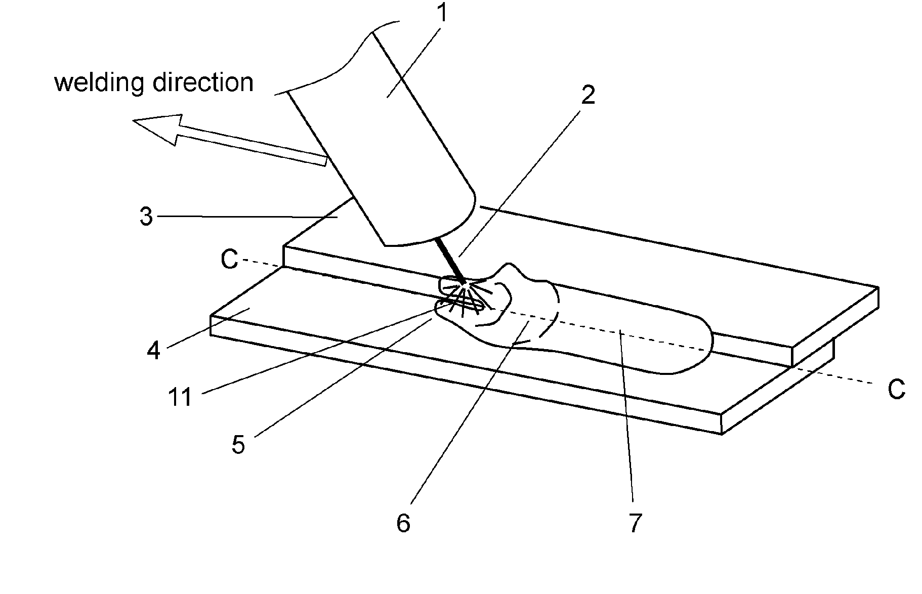
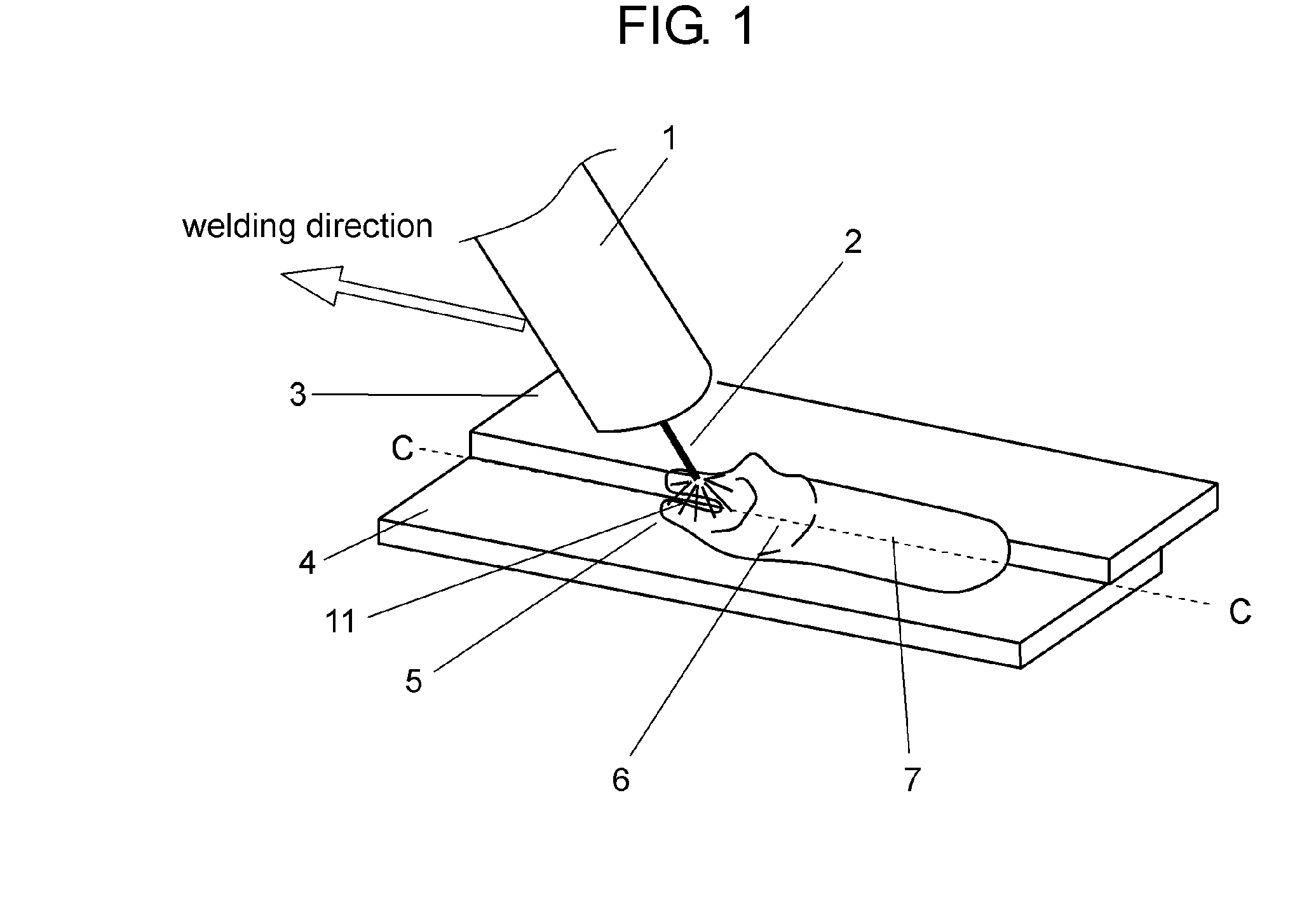
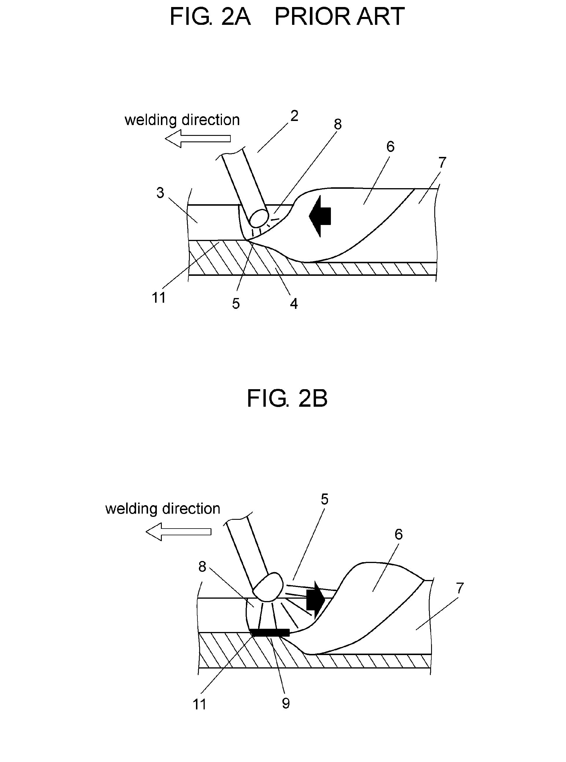
[0027]FIG. 1 shows a welding state in the arc welding control method in accordance with this exemplary embodiment. FIG. 2A is a sectional view (corresponding to the sectional view taken away line C-C of FIG. 1), seen in the horizontal direction, of a welding area in an arc period in accordance with a conventional arc welding control method. FIG. 2B is a sectional view (i.e., the sectional view taken away line C-C of FIG. 1), seen in the horizontal direction, of a welding area in an arc period in accordance with this exemplary embodiment. FIG. 2C shows a waveform of welding current in accordance with a conventional arc welding control method. FIG. 2D shows a waveform of welding current in accordance with arc welding control method of this exemplary embodiment. FIG. 2A relates to FIG. 2C, showing a welding state in first predetermined period 13 in FIG. 2C. Similarly, FIG. 2B relates to FIG. 2D, showing a welding state in first predetermined period 13 in FIG. 2D.

[0028]Throughout the dr...


PUM

PropertyMeasurementUnit
Currentaaaaaaaaaa
Speedaaaaaaaaaa
Currentaaaaaaaaaa

Abstract

As a conventional problem, welding on surface-treated material, such as a zinc-coated steel plate, considerably generates air holes including blowholes and also generates lots of spatters. Present invention provides a method of controlling arc welding performed in a manner that a short-circuit period, in which a short circuit is generated between a welding wire and an object to be welded, and an arc period, in which an arc is generated after release of the short circuit, are repeated alternately. According to the method, welding current is increased from an arc-regeneration-before current to a first welding current at a detection of release of the short circuit such that an increase gradient of the welding current becomes not less than 750 A/msec. This suppresses generation of air holes and spatters in welding work on a surface-treated material, such as a zinc-coated steel plate.

Description

BACKGROUND[0001]1. Technical Field[0002]The present invention relates to a method of controlling arc welding performed in a manner that, with use of a welding wire as a consumable electrode, a short-circuit period (in which a short circuit is generated between the welding wire and an object to be welded) and an arc period (in which an arc is generated after release of the short circuit) are repeated alternately.[0003]2. Background Art[0004]Conventionally, there have been made some suggestions on decrease in correction processes after arc welding by decreasing spatters generated in arc welding. In one known control method, for example, in an early stage of the arc period after arc regeneration, current is controlled so as to have a current value higher than a current value immediately before the arc regeneration. The current control provides an arc length immediately after arc regeneration with stability and suppresses generation of short circuit, resulting in decrease in spatters (s...

Claims


Application Information

Patent Timeline
IPC IPC(8): B23K9/095B23K9/12B23K9/23B23K9/073B23K9/09
CPCB23K9/095B23K9/0732B23K9/124B23K9/23B23K9/092B23K9/073B23K9/09B23K9/173B23K2103/04B23K2101/18B23K2101/34
Inventor KAWAMOTO, ATSUHIROFUJIWARA, JUNJIHIROTA, YUKINORIMATSUOKA, NORIYUKIMATSUI, KAITO
Owner PANASONIC INTELLECTUAL PROPERTY MANAGEMENT CO LTD
Why Eureka
Try Eureka