Method and apparatus for preparing ceramic body segments

Inactive Publication Date: 2014-11-06
ROHM & HAAS CO +1
View PDF8 Cites 0 Cited by
  • Summary
  • Abstract
  • Description
  • Claims
  • Application Information

AI Technical Summary

Benefits of technology

The patent is about a new way to make ceramic logs that are precise and have minimal defects. The method involves using a cutting device with two bleds that create a smooth surface on the log and remove any excess material above it. This process is fast and efficient.

Problems solved by technology

For example, some of the processes disclosed by the references may be limited in the amount of scrap (e.g. length) that can be removed in a single process step, which in turn may increase the time required to produce logs at a given desired segment length.
Also, it is believed that cutting techniques that utilize a single blade, especially as it exits across the end of the work piece, can contribute to the creation of defects.
More explicitly, defects may include cracks or chips (typically greater than about 0.5 mm) in the outer skin layer and / or missing, damaged, or deformed honeycomb walls.

Method used


Image

  • Method and apparatus for preparing ceramic body segments
  • Method and apparatus for preparing ceramic body segments
  • Method and apparatus for preparing ceramic body segments

Examples


example 1

Circular Saw 200

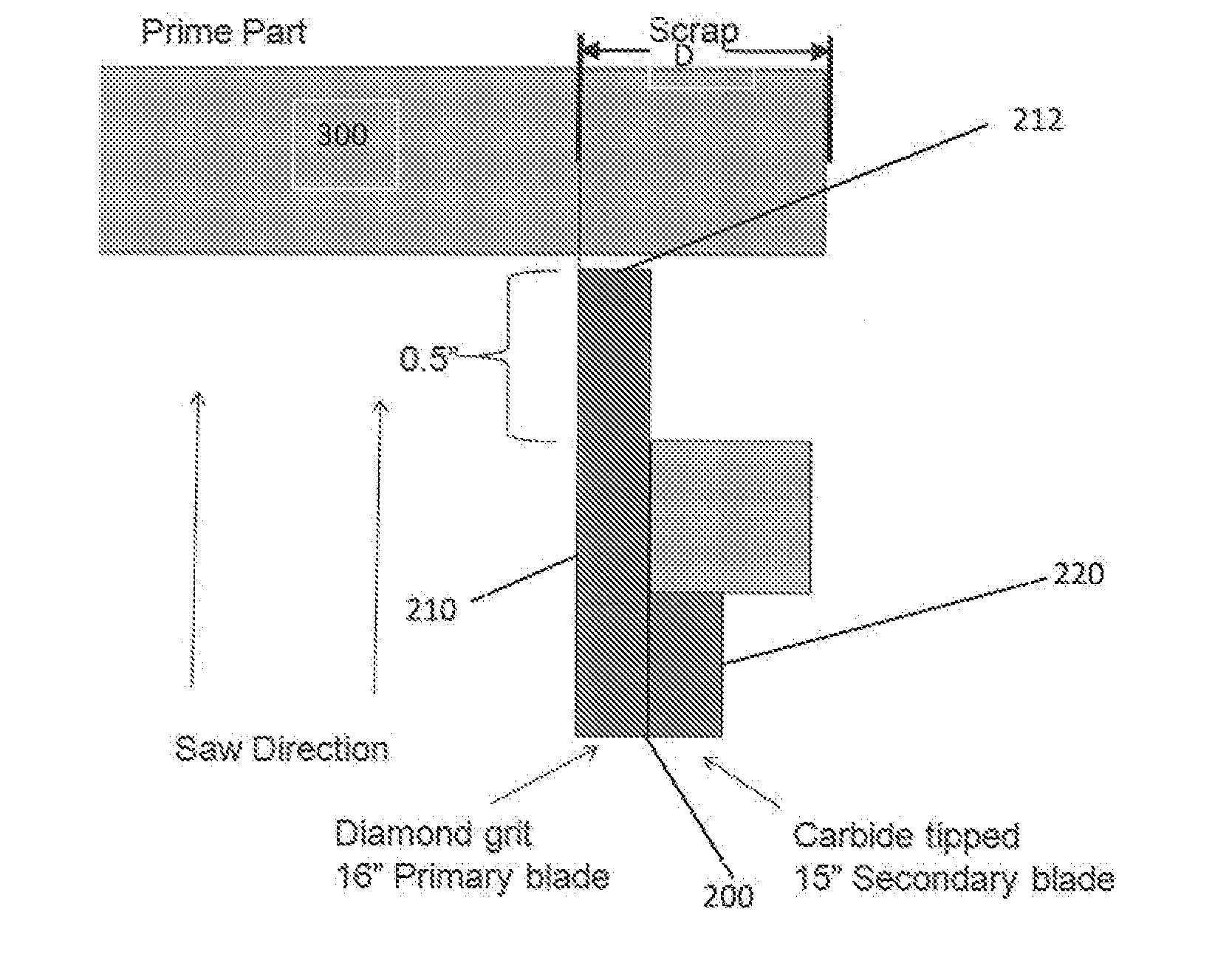
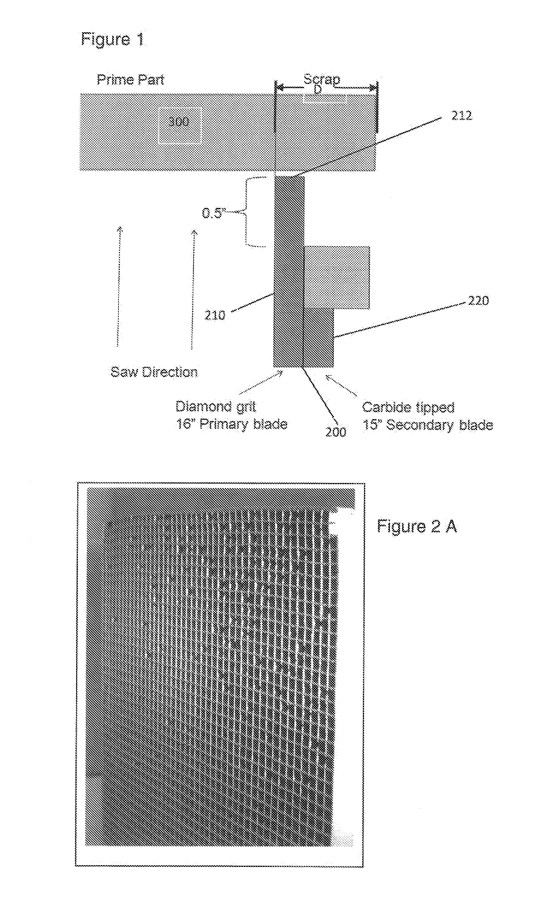
[0047]As an illustrative example, as shown in FIGS. 1, 4A and 4B, a circular saw style ceramic log cutting apparatus 100 is presented. The apparatus 100 includes a dual bladed cutting member 200, a ceramic log 300, a nesting fixture 110, and motors (not shown) that drive the member 200.

[0048]The dual bladed cutting member 200 in this example consists of a first blade 210 and a second blade 220 abutting one another, as illustrated in FIG. 1. In this example, the first blade 210 is a circular blade with a diameter of about 16 in (406 mm) and the second blade with a diameter of about 15.0 in. (381 mm). Both blades rotate about a common axis 9 in the same direction) and a leading edge 222 of the cutting surface of the second blade 220 is off-set inside that of a leading edge 212 of the cutting surface of the first blade 210 by about 0.5 in. (12.5 mm). Blade 210 is an abrasive saw, in this example a diamond grit blade (0.050 in. (1.3 mm)) core thickness and an 80 / 100 diam...

example 2

Band Saw / Reciprocating Saw 500

[0050]As another illustrative example, a band saw / reciprocating saw style ceramic log cutting apparatus 100 is presented. The cutting member 500 is similar to that presented in the circular saw example above in that a leading edge 522 of the cutting surface of the second blade 520 is off-set inside that of a leading edge 512 of the cutting surface of the first blade 510 by about 0.5 in. (12.5 mm). Blade 510 is an abrasive saw, in this example a diamond grit blade (0.050 in. (1.3 mm)) core thickness and an 80 / 100 diamond grit) and blade 520 is a serrated blade with a single sided set, more specifically a carbide tipped blade (0.125 in. kerf (3.2 mm)). The member does not rotate, but has a linear motion (one direction for the band saw and two for the reciprocating saw) of about 1700 m / minute and feed into the log 300 at a rate ranging from about 10 to 40 cm / minute to perform the cutting of the log 300.

example 3

Circular Saw 600

[0051]In an illustrative example, two circular saw style ceramic log cutting methods are presented. In a first set-up (YL11), a log 300 is placed such that the bottom of the log 300 is disposed nearer the bottom of the circular saw 600. In a second set-up (YL14), the log 300 is placed such that it is nearer the axis of rotation of the saw 600, both set-ups as shown in FIG. 3A. Two groups of seven logs 300 each are processed as described in example 1 above, with the location of the log 300 relative to the axis of rotation of the saw 600 being different for each group. Table 1 shows the result and illustrates that the average yield of “defect free” parts is significantly higher when the log is nearer to the axis of rotation of the saw 600. FIG. 38 is a bar chart of the results from Table 1.

TABLE 1PartsPartsTop FaceBottom FaceBilletspassedfailedCrack YieldCrack Yield0.050″ blade02060%75%0.040″ blade41786%86%YL11-106433%67%YL11-2125361%81%YL11-396363%82%YL11-457342%50%YL...


PUM

PropertyMeasurementUnit
Lengthaaaaaaaaaa
Percent by massaaaaaaaaaa
Lengthaaaaaaaaaa

Abstract

A method including providing a ceramic log (300) with a first end and an opposing second end; providing one or more cutting devices (100) comprised of a dual bladed cutting member (200); and removing material by cutting at least the first end with the dual bladed cutting member (200), wherein a first blade (210) of the dual bladed cutting member (200) provides a finished surface and a second blade (220) removes a percentage of scrap above the finished surface. An apparatus (100) for cutting a ceramic log (300).

Description

FIELD OF THE INVENTION[0001]The present invention relates generally to a method and apparatus for preparing one or more ceramic bodies (logs) with an improved end shape profile and to filters prepared from the ceramic bodies. More particularly, to a method and apparatus to cut one or more edge surfaces of the ceramic bodies down to a desired segment length and providing an improved end shape profile.BACKGROUND OF THE INVENTION[0002]Diesel and gasoline engines emit soot particles, very fine particles of carbon and soluble organics as well as typical harmful engine exhaust gases (i.e., HC, CO and NOx). Regulations have been enacted curbing the amount of soot permitted to be emitted. To meet these challenges, soot filters constructed of ceramic bodies have been used. In preferred embodiments, ceramic bodies that include an internal honeycomb structure and at least partially surrounded by a skin layer have been developed.[0003]Manufacturing of these ceramic bodies has typically been acc...

Claims


Application Information

Patent Timeline
IPC IPC(8): B28B11/12
CPCB28B11/12B23D45/10B23D49/003B23D53/005
Inventor SCHUITMAN, ABRAHAM D.VASQUEZ, NESTOR A.STALDER, BLAKE R.OGLE, JAMES R.SACCHETTI, PAUL J.
Owner ROHM & HAAS CO
Why Eureka
Try Eureka