Lens array, light source device, projector and light source device fabrication method

a technology of light source device and fabrication method, which is applied in the direction of manufacturing tools, lighting and heating apparatus, instruments, etc., can solve the problems of adjusting work that has to be performed for a certain length of time, and achieve the effect of facilitating the alignment of optical axes

Active Publication Date: 2013-03-07
CASIO COMPUTER CO LTD
View PDF4 Cites 23 Cited by
  • Summary
  • Abstract
  • Description
  • Claims
  • Application Information

AI Technical Summary

Benefits of technology

[0010]The invention has been made in view of the aforesaid problem which is inherent in the related art, and an object of the invention is to provide a lens array which facilitates the alignment of optical axes of light source elements with optical axes of lenses, alight source device that employs the lens array, a projector that employs the light source device, and a light source fabrication method.

Problems solved by technology

However, in the light source device proposed by JP-A-05-88062, the adjustment of optical axes of lenses and light emitting elements needs to be implemented by adjustment screws, and therefore, a certain length of time has had to be spent in performing the adjusting work.

Method used


Image

  • Lens array, light source device, projector  and light source device fabrication method
  • Lens array, light source device, projector  and light source device fabrication method
  • Lens array, light source device, projector  and light source device fabrication method

Examples


Embodiment Construction

[0043]Hereinafter, am embodiment of the invention will be described by reference to the drawings.

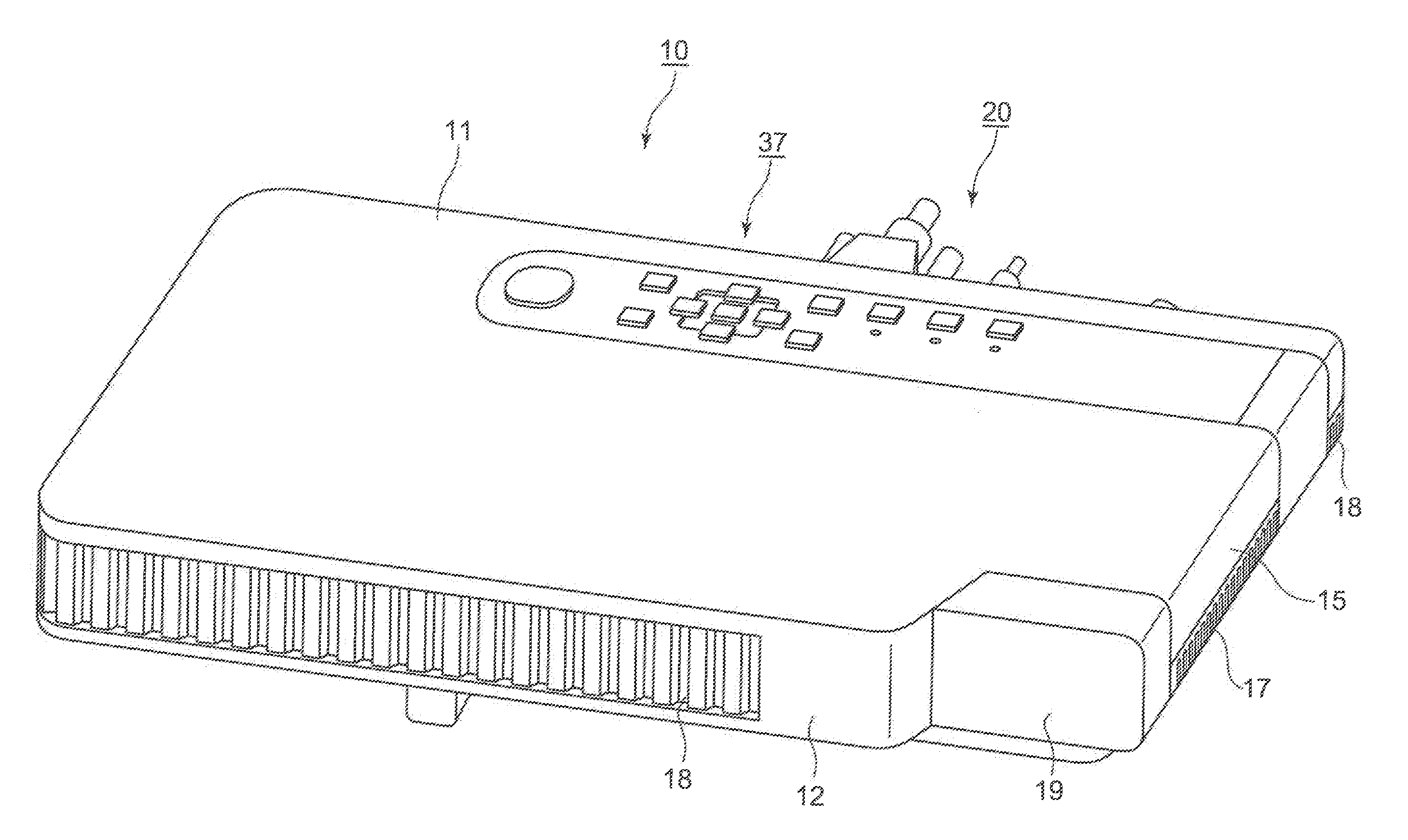
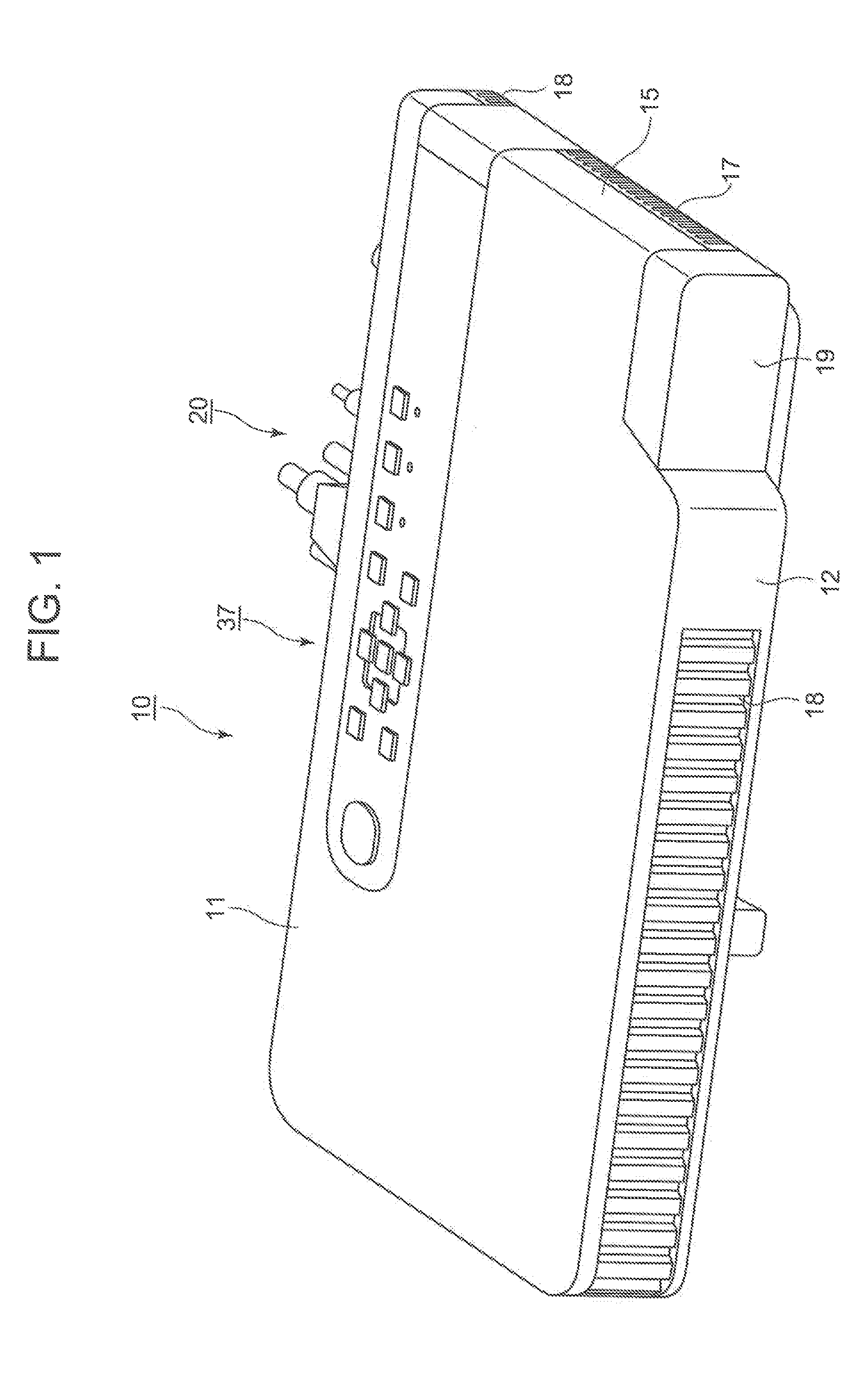
[0044]FIG. 1 is a perspective view showing an external appearance of a projector 10.

[0045]It should be noted that when referred to with respect to the projector 10 in this embodiment, left and right denote, respectively, left and right directions with respect to a projecting direction, and front and rear denote, respectively, front and rear directions with respect to a direction towards a screen and a traveling direction of a pencil of light.

[0046]Additionally, as shown in FIG. 1, the projector 10 has a substantially rectangular parallelepiped shape and has a lens cover 19 which covers a projection opening which is laid to a side of a front side panel 12 which is referred to as a front side panel of a projector casing. Additionally, a plurality of outside air inlet ports 18 are formed in the front side panel 12.

[0047]Further, although not shown, the projector 10 includes an Ir reception ...


PUM

PropertyMeasurementUnit
optical axisaaaaaaaaaa
diameteraaaaaaaaaa
lengthaaaaaaaaaa

Abstract

A lens array which facilitates the alignment of optical axes of light source elements with optical axes of lenses, a light source device that employs this lens array, a projector that employs this light source device and a light source device fabrication method are provided. A lens array 73 is an integrated assembly of a plurality of lens portions 73b which collect individually light from a plurality of light source elements and has cylindrical portions 73c for positioning the plurality of light source elements on a light entrance side of the individual lens portions 73b.

Description

CROSS-REFERENCE TO RELATED APPLICATION[0001]This application is based upon and claims the benefit of priority under 35 USC 119 of Japanese Patent Application No. 2011-194524 filed on Sep. 7, 2011, the entire disclosure of which is incorporated herein by reference.BACKGROUND OF THE INVENTION[0002]1. Field of the Invention[0003]The present invention relates to a lens array, a light source device that employs the lens array, a projector that employs the light source device, and a fabrication method of the light source device.[0004]2. Description of the Related Art[0005]In these days, data projectors are used on many occasions as image projection units which project images including images of a screen of a personal computer and video images, as well as images based on image data which are stored in a memory card on to a screen. In these projectors, light emitted from a light source is collected on to a micromirror display element called a digital micromirror device (DMD) or a liquid cry...

Claims


Application Information

Patent Timeline
Patent Type & Authority Applications(United States)
IPC IPC(8): G03B21/14F21V5/04B23P11/00G02B27/12
CPCB23P11/00F21V5/04G02B27/12G02B3/0075Y10T29/49826G02B27/141F21V7/0083G03B21/2013G03B21/2033G02B27/1033
Inventor YOSHIDA, KAORU
Owner CASIO COMPUTER CO LTD
Why Eureka
Try Eureka