
Magnetic recording reproducing apparatus and magnetic recording medium

Inactive Publication Date: 2013-03-07
SHARP KK
View PDF5 Cites 7 Cited by
  • Summary
  • Abstract
  • Description
  • Claims
  • Application Information

AI Technical Summary

Benefits of technology

The present invention aims to prevent a decrease in the recording rate for rewriting and minimize reproduction errors when using a Shingle recording technique for densely recording. The technical effects of this invention are improved efficiency and reliability in magnetic recording.

Problems solved by technology

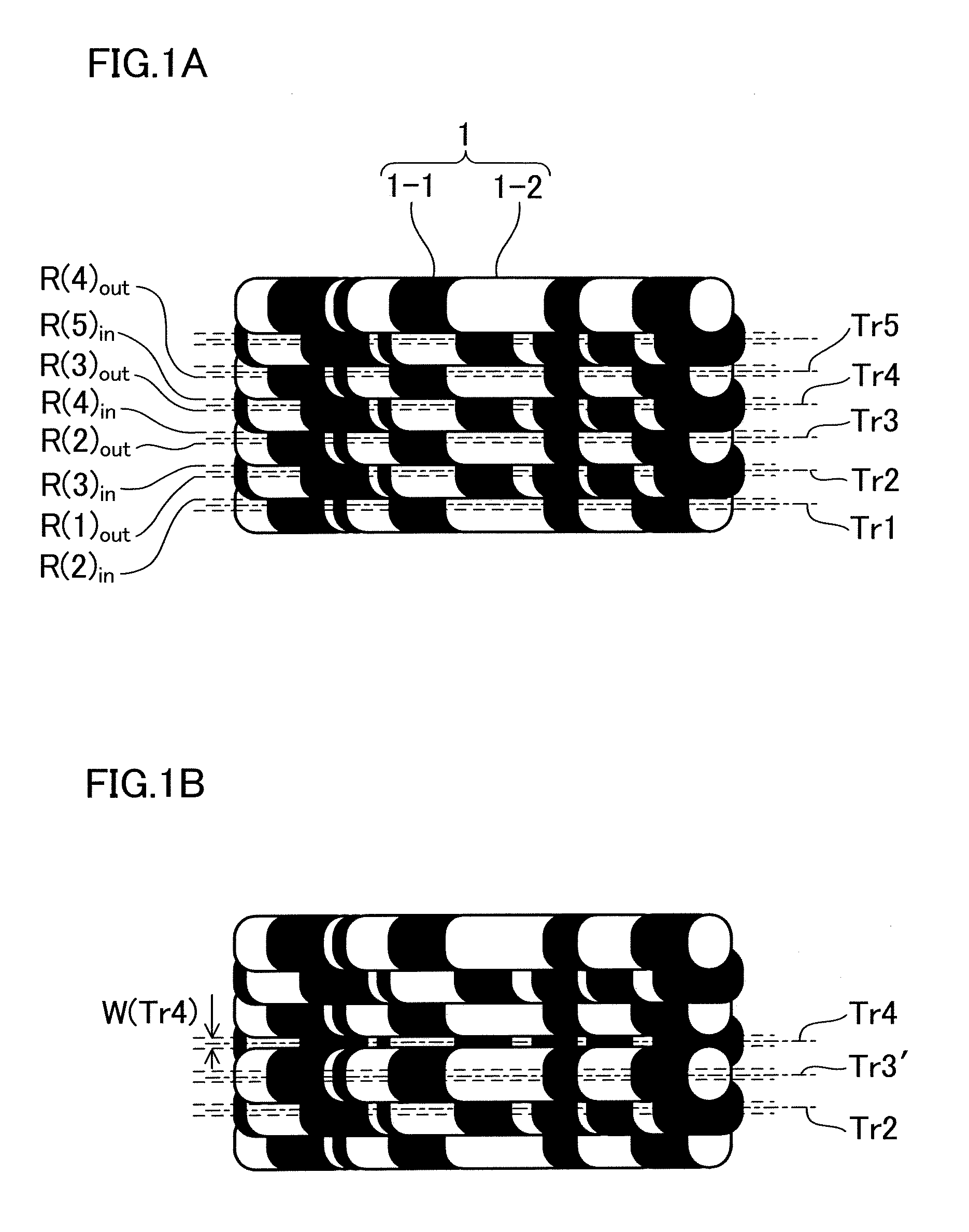
On the other hand, a track Tr103 is overwritten with the recording column for forming the Tr102′, and an attempt to reproduce the track Tr103 under such a condition will result in a reproduction error.

Method used


Image

  • Magnetic recording reproducing apparatus and magnetic recording medium
  • Magnetic recording reproducing apparatus and magnetic recording medium
  • Magnetic recording reproducing apparatus and magnetic recording medium

Examples


first embodiment

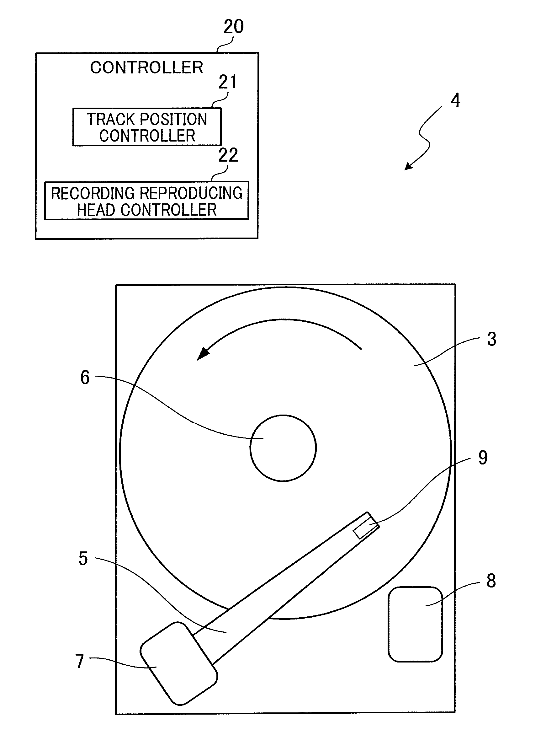
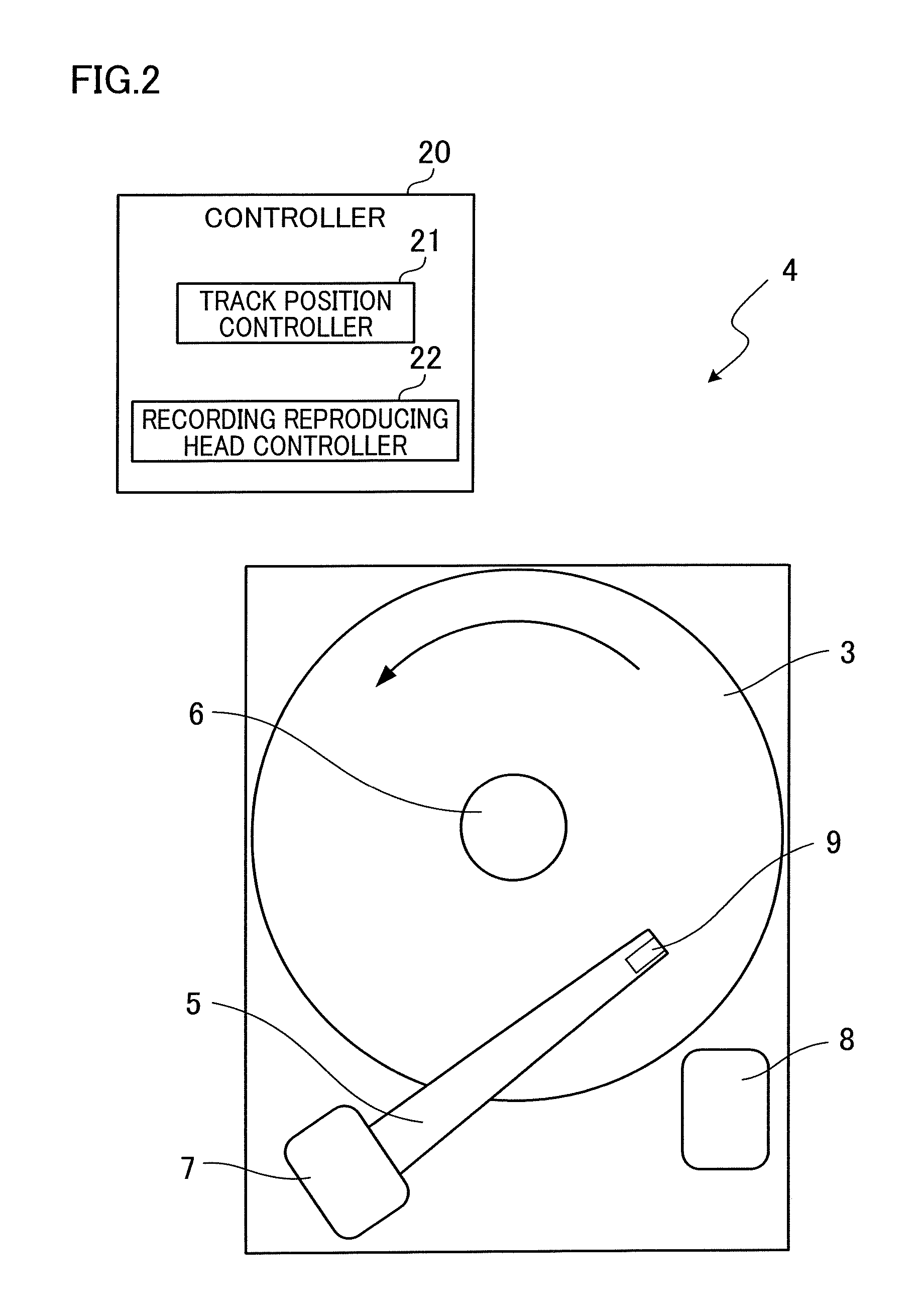
[0022]The following describes a first embodiment of present invention. As shown in FIG. 2, a magnetic recording reproducing apparatus 4 of the present embodiment includes: a suspension 5, a spindle 6, a voice coil motor 7, a ramp mechanism 8, a recording reproducing head 9, and a controller 20 which controls the suspension 5, the voice coil motor 7, and the recording reproducing head 9. Note that FIG. 2 shows the magnetic recording reproducing apparatus 4 with a disc-shaped magnetic recording medium 3. The structure of the magnetic recording medium 3, the recording and reproduction method of the magnetic recording medium 3 by the magnetic recording reproducing apparatus 4, and the details of the controller 20 are explained later.

[0023]The suspension 5 has one end portion fixed to the voice coil motor 7 and another end portion far from the voice coil motor 7 having a recording reproducing head 9 which applies a magnetic field to the magnetic recording medium 3. The spindle 6 rotates ...

second embodiment

[0049]Next, a second embodiment of the present invention is described. Parts and members that are identical to those of the first embodiment are given the same reference numerals, and no further description is provided for them.

[0050]FIG. 5 shows schematically a magnetic recording medium 3 of the present embodiment. FIG. 6 provides a view in which a part of FIG. 5 is enlarged and a part of the same is omitted. As shown in FIG. 5 and FIG. 6, the magnetic recording medium 3 has a tracking pattern 12 (burst pattern) which is a magnetization pattern for tracking each track on the magnetic recording medium 3. The tracking pattern 12 is formed by a servo track writer (STW) or the like in the process of manufacturing the magnetic recording reproducing apparatus 4. The magnetic recording medium 3 before being built into the magnetic recording reproducing apparatus 4 is set to an STW having a magnetic recording head for STW. A magnetic field is then applied to the magnetic recording medium 3...


PUM


Abstract

In an information recording area of a disc-shaped magnetic recording medium, recording columns adjacent to each other relative to a radial direction are formed so as to partially overlap with each other in the radial direction. Each recording column has an overlapping portion which partially overlaps with either of the adjacent recording columns in the radial direction, and a non-overlapping portion which does not overlap with any of the recording columns in the radial direction.

Description

CROSS REFERENCE TO RELATED APPLICATION[0001]The present application claims priority from Japanese Patent Application No. 2011-194646, which was filed on Sep. 7, 2011, the disclosure of which is herein incorporated by reference in its entirety.BACKGROUND OF THE INVENTION[0002]1. Field of the Invention[0003]The present invention relates to a magnetic recording reproducing apparatus and a magnetic recording medium, which adopt a Shingle recording technology and capable of densely recording information.[0004]2. Description of the Related Art[0005]Improvement in high quality pictures and images causes a considerable increase in the volume of information handled by a user. For the purpose of realizing a larger capacity magnetic recording apparatus so-called HDD (Hard Disk Drive), approaches for increasing the surface recording density have been discussed. One high-density magnetic recording technology that seems to be promising is a Shingle recording technique which is disclosed in Japane...

Claims


Application Information

Patent Timeline
IPC IPC(8): G11B21/02G11B5/82
CPCG11B5/012G11B2005/0005G11B5/09
Inventor SAKAI, TOSHIHIKOMURAKAMI, YOSHITERU
Owner SHARP KK
Learn More