Spindle motor

a spindle motor and spindle shaft technology, applied in the direction of bearings, shafts and bearings, bearings, etc., can solve the problems of reducing the height of the sleeve in an axial direction, and reducing the life of the spindle motor, so as to prevent an oil shortage phenomenon, maximize the amount of stored oil, and improve the rigidity of the bearings

Inactive Publication Date: 2013-03-07
SAMSUNG ELECTRO MECHANICS CO LTD
View PDF4 Cites 2 Cited by
  • Summary
  • Abstract
  • Description
  • Claims
  • Application Information

AI Technical Summary

Benefits of technology

[0013]An aspect of the present invention provides a spindle motor capable of preventing a hub from being separated from a shaft due to an external impact, maximizing an amount of stored oil, and preventing an oil shortage phenomenon due to oil leakage, to improve bearing rigidity.

Problems solved by technology

When a temperature of the spindle motor according to the related art rises, oil may deviate from a normal oil interface due to oil expansion, which causes oil leakage, and accordingly, spindle motor performance may be deteriorated.
Particularly, in the case that an external impact is applied to the spindle motor, oil leakage may cause serious problems therein, thereby reducing a lifespan thereof.
A height of the sleeve in an axial direction may be relatively reduced due to space occupied by the stopper, such that rigidity of the bearing may be weakened.
Furthermore, in the case that an external impact is applied to the spindle motor, it may be difficult to maintain rigidity of a hub in the structure of the stopper according to the related art, such that the hub may often be separated from the shaft.

Method used


Image

  • Spindle motor
  • Spindle motor
  • Spindle motor

Examples


Embodiment Construction

[0029]Embodiments of the present invention will now be described in detail with reference to the accompanying drawings. However, it should be noted that the spirit of the present invention is not limited to the embodiments set forth herein and those skilled in the art and understanding the present invention could easily accomplish retrogressive inventions or other embodiments included in the spirit of the present invention by the addition, modification, and removal of components within the same spirit, but those are to be construed as being included in the spirit of the present invention.

[0030]Further, like reference numerals will be used to designate like components having similar functions throughout the drawings within the scope of the present invention.

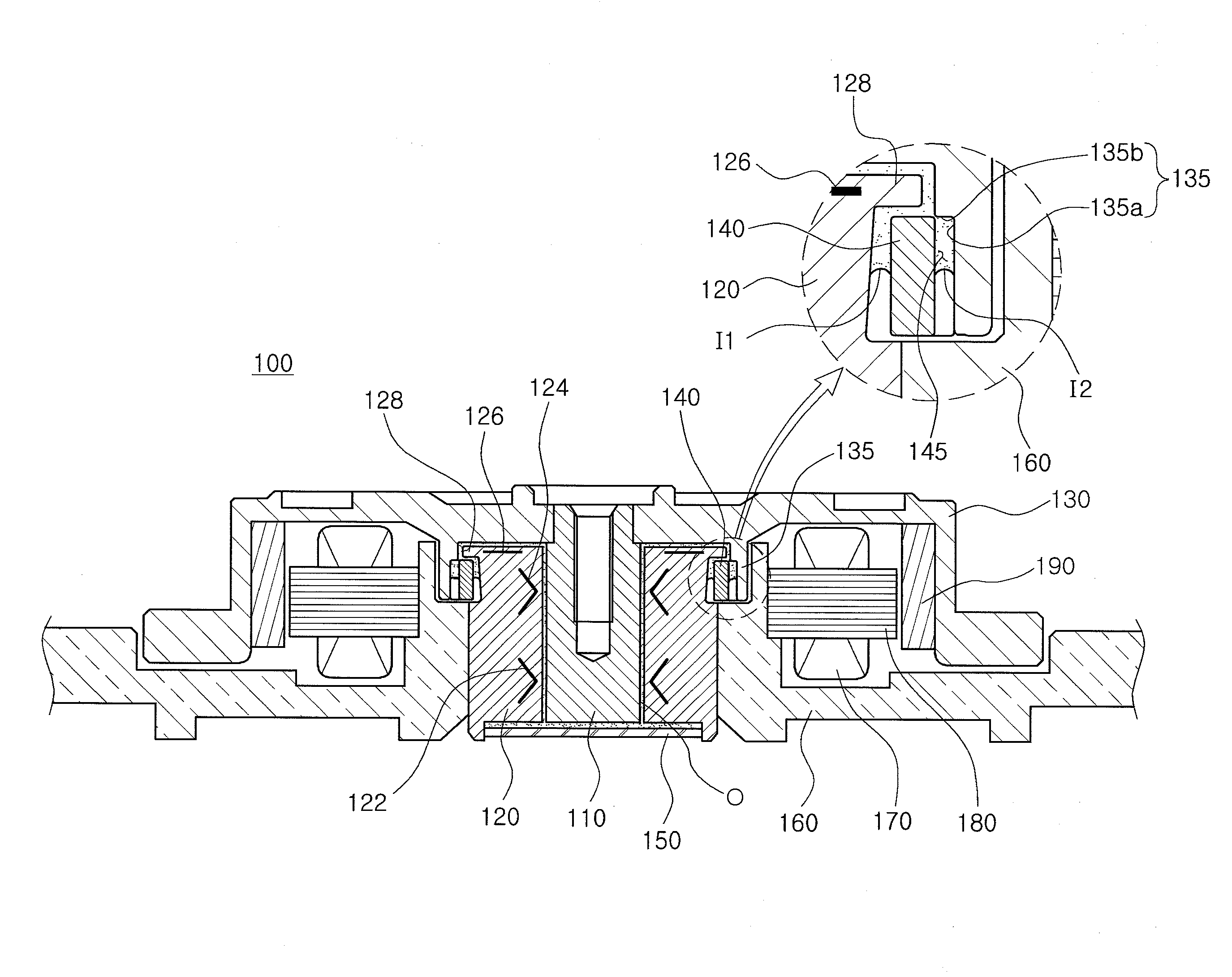
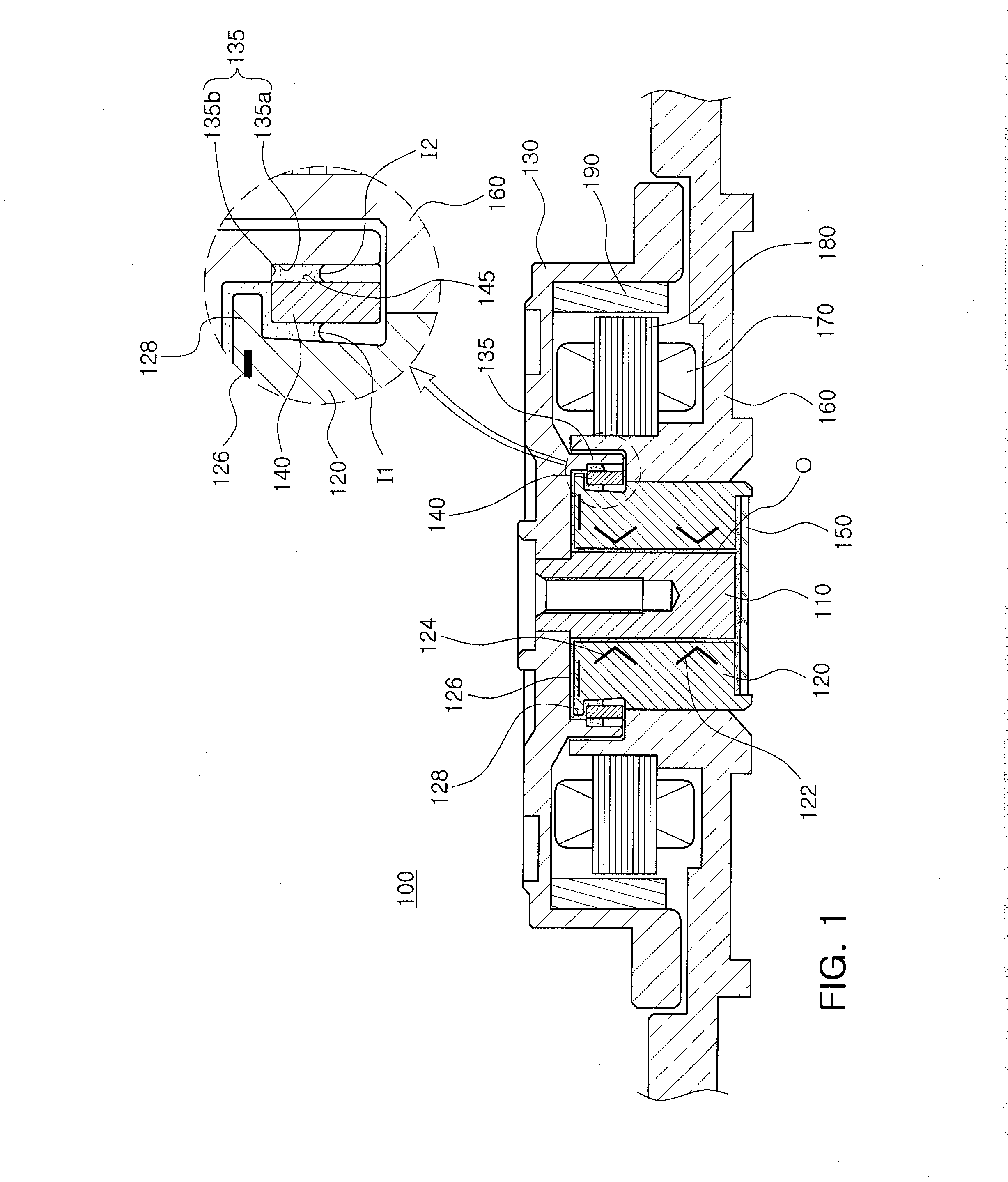
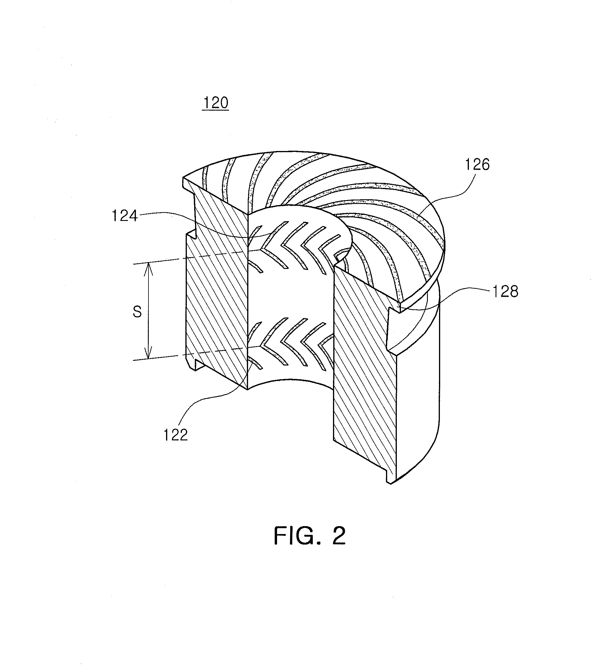
[0031]FIG. 1 is a schematic cross-sectional view showing a spindle motor according to an embodiment of the present invention; FIG. 2 is a schematic cut-away perspective view showing a sleeve provided in the spindle motor according...


PUM


Abstract

There is provided a spindle motor including: a hub moving together with a shaft; a sleeve supporting the shaft with oil; a stopper provided in the hub to thereby prevent excessive floating of the shaft; and oil storage parts formed on the stopper so as to be in communication with the outside, providing a storage space for the oil, and allowing an oil interface to be formed therein.

Description

CROSS-REFERENCE TO RELATED APPLICATIONS[0001]This application claims the priority of Korean Patent Application No. 10-2011-0090675 filed on Sep. 7, 2011, in the Korean Intellectual Property Office, the disclosure of which is incorporated herein by reference.BACKGROUND OF THE INVENTION[0002]1. Field of the Invention[0003]The present invention relates to a spindle motor, and more particularly, to a spindle motor capable of being used in a hard disk drive (HDD) rotating a recording disk.[0004]2. Description of the Related Art[0005]A hard disk drive (HDD), an information storage device, reads data stored on a disk or writes data to a disk using a read / write head.[0006]The hard disk drive requires a disk driving device capable of driving the disk. As the disk driving device, a spindle motor is used.[0007]In the spindle motor, a fluid dynamic bearing is in common use. A shaft, a rotating member of the fluid dynamic bearing, and a sleeve, a fixed member thereof, include oil interposed ther...

Claims


Application Information

Patent Timeline
Patent Type & Authority Applications(United States)
IPC IPC(8): F16C17/04
CPCF16C33/743F16C33/107F16C33/745F16C2370/12G11B19/20
Inventor KIM, JIN SAN
Owner SAMSUNG ELECTRO MECHANICS CO LTD
Why Eureka
Try Eureka