Looped material band provided with a splice

a technology of looped material and splice, which is applied in the direction of driving belts, belt fastenings, v-belts, etc., can solve the problems of affecting the mechanical resistance and fatigue life properties of production equipment, and affecting the profitability of production equipment. , to achieve the effect of preserving mechanical resistance and fatigue life properties

Active Publication Date: 2013-03-14
TANALS S
View PDF4 Cites 10 Cited by
  • Summary
  • Abstract
  • Description
  • Claims
  • Application Information

AI Technical Summary

Benefits of technology

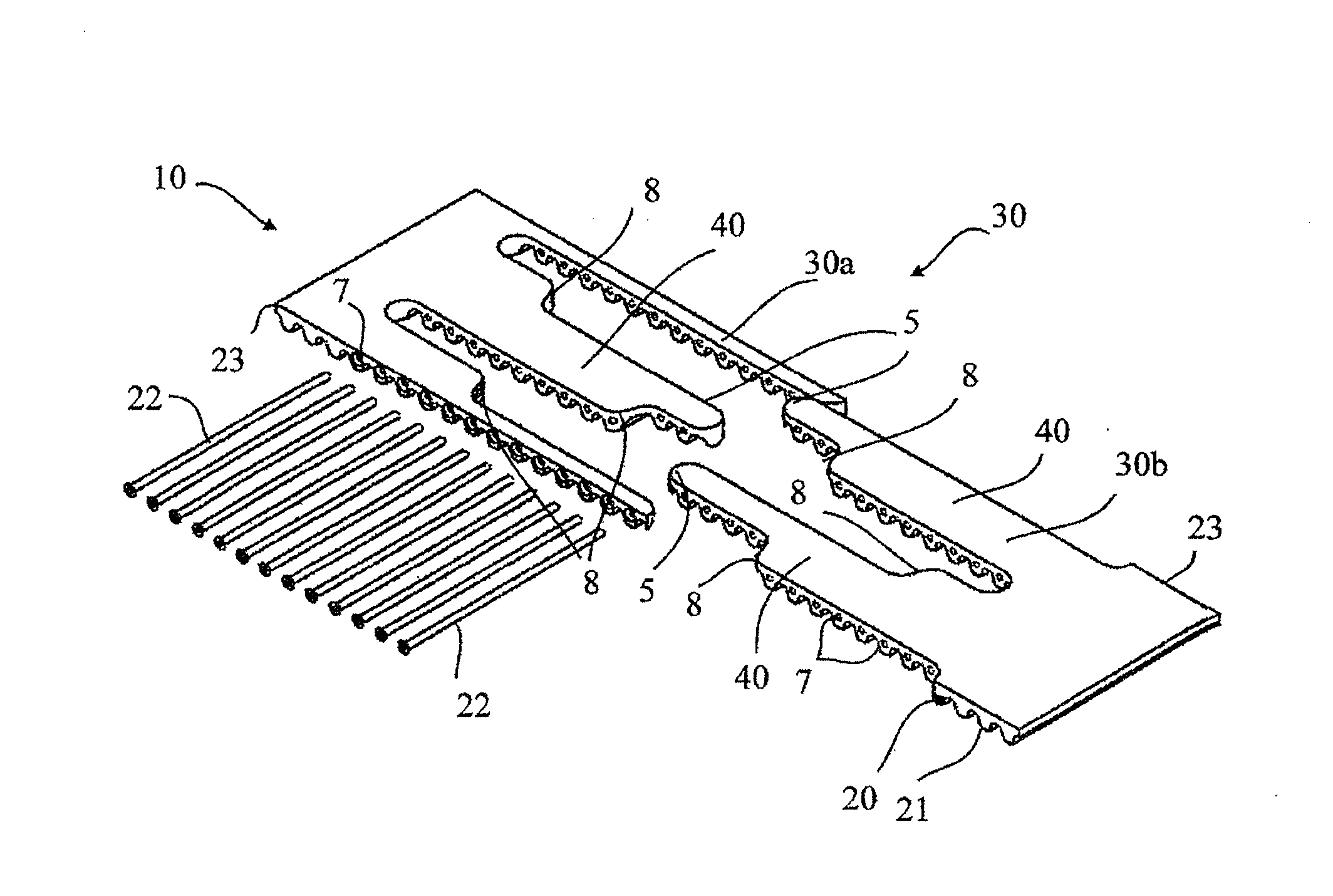
[0008]The present invention aims to remedy these disadvantages by offering a looped material band having at least one reversible splice area arranged so as to allow its assembly and disassembly on site and to preserve the mechanical resistance and fatigue life properties of the looped material band, so that it can compete in terms of resistance with any other ma

Problems solved by technology

They nevertheless have the disadvantage that their installation on a machine, as well as their removal for replacement, requires the disassembly of the machine, or even the intervention of the manufacturer of the machine, imposing a stoppage of the machine, which is detrimental to the profitability of the production equipment.
At the moment, the handling operations of such transmission belts, whether of the PolyChain® type or of any other type, having the shape of endless sleeves, show consequently to be particularly laborious, time-consuming and costly.
The reversible splice solutions commonly used in the area of conveyor belts and described in a number of publications do not show to be totally satisfactory when they are transposed as such on power transmission belts such as those described previously, which presuppose, as mentioned, a structure able to resist mechanical stress, due in particular to the high power torques to transmit and to a high rotational speed, both being markedly higher than those found in the conveying branch.
The main disadvantage of this solution, when it is implemented within the framework of a power transmission belt, is due to the fact that the shape offered for said teeth has sharp angles.
Even though such a feature is very well adapted for a conveyor belt, classically made out of a material such as extruded polyurethane reinforced with longitudinal steel tensile cords, it appears that the presence of any sharp ang

Method used


Image

  • Looped material band provided with a splice
  • Looped material band provided with a splice
  • Looped material band provided with a splice

Examples


first embodiment

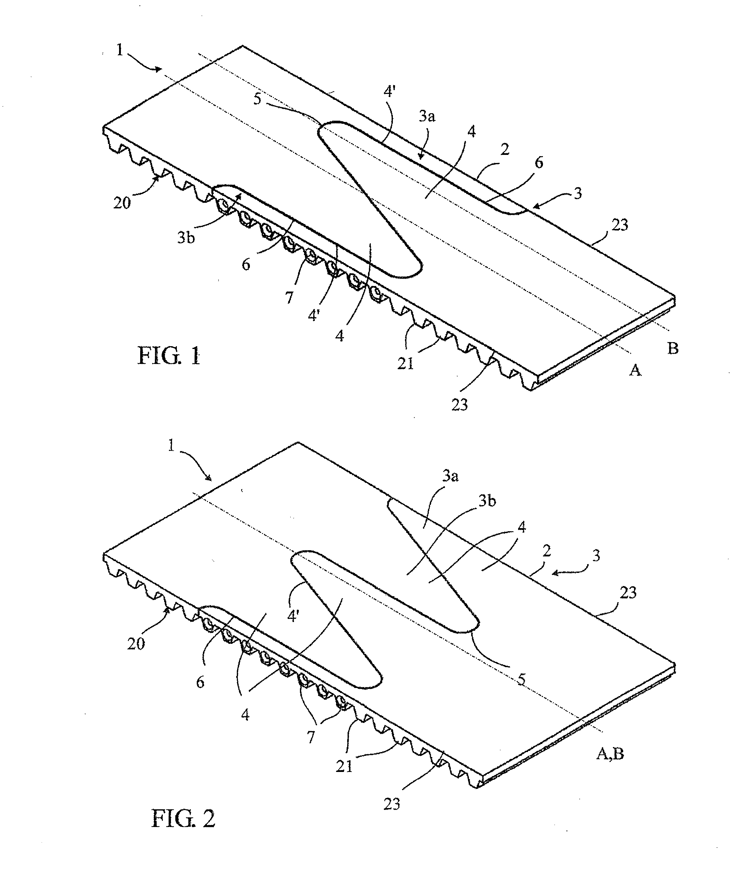
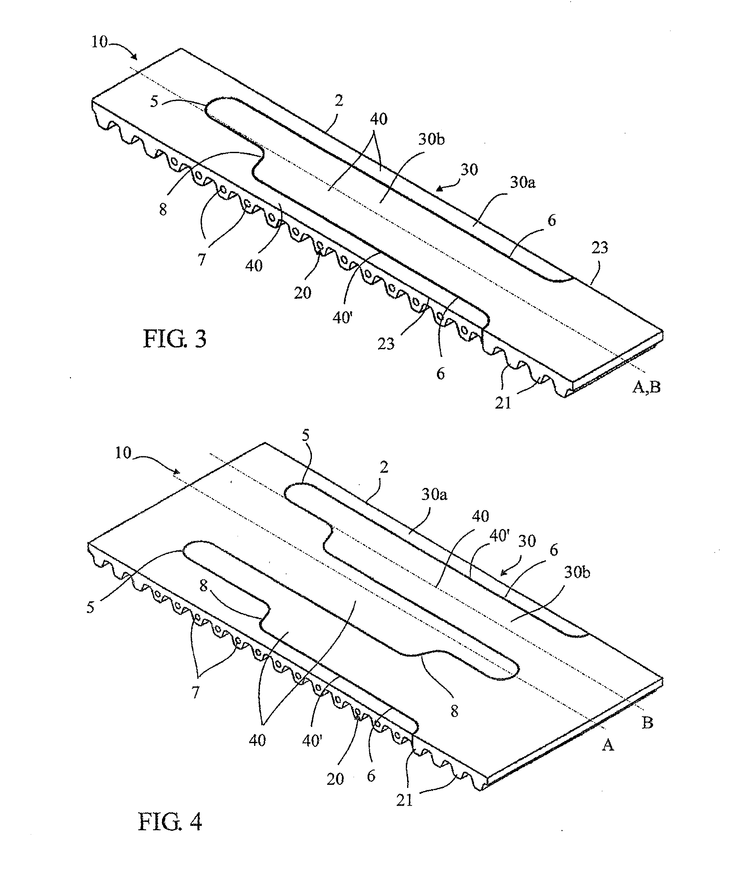
[0040]FIG. 9 illustrates a flat strip 2 to form the looped material band 120 illustrated in FIG. 10, comprising two splice areas 30, made for example according to the variant illustrated in FIGS. 3 to 5 or according to any other equivalent variant such as that illustrated in FIGS. 1 and 2, offset laterally and extending each on a width smaller then half the width of the flat strip 2. So, when the ends of the flat strip 2 are assembled to form the material band 120, the two splice areas 30 are aligned in the width of said band, arranged on both sides of the centerline A of the flat strip 2, and delimit between them a continuous median portion 9, without splice, offering the same advantages in terms of resistance as the previous examples.

second embodiment

[0041]FIG. 11 illustrates a flat strip 2 to form the looped material band 130 illustrated in FIG. 12 comprising three splice areas 30, made for example according to the variant illustrated in FIGS. 3 a to 5 or according to any other equivalent variant such as that illustrated in FIGS. 1 and 2, offset laterally, aligned in a chevron arrangement and extending over a width smaller than the third of the width of the flat strip 2. So, when the ends of the flat strip 2 are assembled to form the material band 130, the three splice areas 30 are aligned in the width of said band, arranged symmetrically with respect to the centerline A of the flat strip 2, and delimit between them two continuous intermediate portions 9, without splice, offering the same advantages in terms of resistance as the previous examples. Furthermore, this symmetrical construction allows balancing the efforts in the material strip 130 obtained, which suits therefore particularly for high-speed or high-power installatio...


PUM


Abstract

A looped material band (100) which includes at least one flat strip (2) having two reversible splice areas (3) in which the serrations (3a, 3b) only extend along a part of its width so that, when the material band is assembled in a loop around two pulleys (10a, 10b), the strands of the material band, which extend respectively between the two pulleys, are continuous and without any splice at least along a portion (9) of their width, regardless of the rotational position of the looped material band.

Description

[0001]This application claims priority from French patent application serial no. 11 / 57974 filed Sep. 8, 2011.FIELD OF THE INVENTION[0002]The present invention relates to a looped material band such as in particular a power transmission belt, a conveyor belt, a conveyor or similar, including at least one flat strip having at least one reversible splice area allowing assembling and disassembling said looped material band, said reversible splice area comprising at least two serrations with complementary shapes that can be engaged into each other, provided each in the plane of an end of said flat strip, said serrations comprising each at least one tooth delimited by a perimeter and arranged in order to be crossed, after engaging them, by at least one removable transversal connecting pin that allows locking and unlocking said splice area.BACKGROUND OF THE INVENTION[0003]Many areas of industry use looped material bands, either as power transmission elements such as belts or as transport e...

Claims


Application Information

Patent Timeline
IPC IPC(8): B65G15/30F16G3/00
CPCF16G1/28F16G3/02F16G3/00
Inventor FREY, PIERRE-REGIS
Owner TANALS S
Why Eureka
Try Eureka