High power inductor and ignition transformer using planar magnetics

a technology of inductor and ignition transformer, which is applied in the manufacture of coils, basic electric elements, magnetic bodies, etc., can solve the problems of difficult manufacturer redundancy, significant impact on the size and cost of transformers, and unit to unit reliability variance, etc., and achieves the effect of large winding

Inactive Publication Date: 2013-03-14
HYPERTHERM INC
View PDF6 Cites 13 Cited by
  • Summary
  • Abstract
  • Description
  • Claims
  • Application Information

AI Technical Summary

Benefits of technology

[0014]Each of the aspects above can further employ one or more of the following advantages.
[0021]In some embodiments, the first planar coil and the second planar coil are cut so that a magnetically conductive core can be used to hold multiple planar coils. An air bobbin can be used to hold two or more planar inductors in place. Connecting the combination of the first planar coil, the bridge and the second planar coil to a combination of a third planar coil, a second bridge and a fourth planar coil through the connection points can create a larger winding.

Problems solved by technology

Custom made plastic bobbins have a significant impact on the size and cost of a transformer.
Furthermore, the windings can often have fractional turns and imprecise winding methods results in unit to unit start reliability variance.
Further, the use of custom made bobbins can make it difficult to have manufacturer redundancy, resulting in supply chain vulnerability.
Inductors and transformers can account for a significant portion of the power supply cost.
However, using PCBs in lieu of copper wires still results in other issues, such as overheating and cost at high currents (e.g., 80 amps or higher).

Method used


Image

  • High power inductor and ignition transformer using planar magnetics
  • High power inductor and ignition transformer using planar magnetics
  • High power inductor and ignition transformer using planar magnetics

Examples


Embodiment Construction

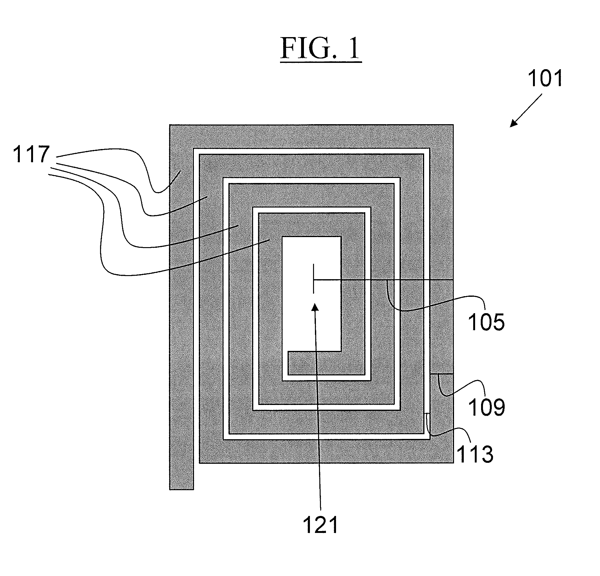
[0032]FIG. 1 shows a planar coil 101. The planar coil 101 has a coil width 105, a turn width 109, an inter-turn spacing 113, and a turn number 117. The coil width 105 is a distance from a center of the planar coil to a furthest edge of the planar coil 101. The turn width 109 is a width of a turn of the planar coil 101. The inter-turn spacing 113 is a gap between adjacent turns of the planar coil 101. The turn number 117 is the number of turns the planar coil 101 takes. At or around the center of the planar coil 101 is a hole 121. A magnetically conductive core (see below) can be inserted into the hole 121.

[0033]The planar coil 101 can be made from a conductive material, such as copper or aluminum. In some embodiments, the planar coil 101 is made solely of a conductive material. The conductive material is cut, etched, or similarly manipulated in order to achieve a desired shape and size. The conductive material can be cut, etched, or similarly manipulated to have the turn diameter 10...


PUM

PropertyMeasurementUnit
thermally conductiveaaaaaaaaaa
conductiveaaaaaaaaaa
thicknessaaaaaaaaaa

Abstract

Described are methods and systems for using a planar inductor that includes a magnetically conductive core, a first planar coil and a second planar coil. The first and second planar coils are attached to a first bridge, located about the core, and are composed of a conductive material. The first and second planar coils have at least one thermally conductive surface exposed to cooling fluid. The first planar coil, the first bridge and the second planar coil are formed from a first unitary section of conductive material. The second planar coil is positioned relative to the first planar coil in a spaced relationship, which is defined by a thickness of the first bridge. An upper surface of the first planar coil is oriented toward a lower surface of the second planar coil to define a first cooling channel between the first planar coil and the second planar coil.

Description

RELATED APPLICATIONS[0001]This application claims the benefit of and priority to U.S. Provisional Application No. 61 / 505,476, filed Jul. 7, 2011, the entirety of which is hereby incorporated herein by reference.FIELD OF THE INVENTION[0002]This invention relates generally to inductors and ignition transformers using planar magnetics.BACKGROUND OF THE INVENTION[0003]Magnetic components such as inductors and transformers are used in power supply designs for various devices, including plasma cutting power supplies. High voltage ignition transformers form an integral part of the high voltage high frequency (“HVHF”) circuits used in plasma cutting systems. Traditionally, these types of transformers are fabricated using custom made plastic bobbins that ensure appropriate inter-winding spacing and clearance to meet regulatory and functional specifications. The windings are typically wound manually and need to be done precisely in order to meet the self inductance and coupling factor require...

Claims


Application Information

Patent Timeline
Patent Type & Authority Applications(United States)
IPC IPC(8): H01F27/08H01F41/04
CPCH01F27/2804H01F27/2847Y10T29/4902Y10T29/49073H01F27/2876
Inventor KAMATH, GIRISH R.LEBLANC, NORMANCHIN, WAYNETILLMAN, PAUL
Owner HYPERTHERM INC
Why Eureka
Try Eureka