Method and Apparatus For Winding up Coreless and Soft-Core Rolls of Film Materials

a technology of coreless and soft cores, applied in the direction of filament handling, thin material handling, web handling, etc., can solve the problems of irregular distribution of internal stresses, difficult to properly unwind the stretched film from a roll, and difficulty in winding coreless rolls or winding up the film on a soft tubular core. the effect of winding and unwinding the same film

Active Publication Date: 2008-12-25
NOEL
View PDF7 Cites 1 Cited by
  • Summary
  • Abstract
  • Description
  • Claims
  • Application Information

AI Technical Summary

Benefits of technology

[0017]The main object of this invention is to provide a method and an apparatus for winding up coreless and soft-core rolls of film materials, whereby it is possible to adequately obviate the aforementioned problems, improving both the winding and the unwinding of the same film from a roll.

Problems solved by technology

However, in winding up rolls of film, and in their subsequent use, several problems arise which have been variously tackled and variously solved in the past.
In fact, with usual smooth films, it is difficult to wind coreless rolls or to wind up the film on a soft tubular core, which has a stable shape, due to their tendency to implode.
Moreover, pre-stretched films or elastically yielding films retain an elastic memory which over time makes them to shrink in such a way that the outer turns generate a pressure on the inner turns, deforming and making them adhere to one another, thereby preventing or making it difficult to properly unwind the stretched film from a roll.
This solution has however a number of drawbacks, such as for example the difficulty in obtaining evenly wound rolls having a constant diameter; in fact the deformation of the film, necessary to form the small embossed pockets for entrapping the air, tends to generate irregularly distributed internal stresses, with the consequent formation of creases in the film during the winding up of the roll.
Moreover, since the air remains entrapped in the individual pockets, without any possibility of venting, the rolls of film have a final diameter, which is still considered to be excessive, in relation to the quantity of wound up film.
Lastly, the winding up of coreless as soft-core rolls by the methods and apparatuses currently in use, leads to the formation of rolls having very large diameters, with consequent higher storage and transport costs due to the larger volume incurred by the same rolls.

Method used


Image

  • Method and Apparatus For Winding up Coreless and Soft-Core Rolls of Film Materials
  • Method and Apparatus For Winding up Coreless and Soft-Core Rolls of Film Materials
  • Method and Apparatus For Winding up Coreless and Soft-Core Rolls of Film Materials

Examples


first embodiment

[0044]With reference to the figures from 1 to 4, a description is given of the apparatus and of the method for winding up coreless or soft-core rolls of film material, according to the invention.

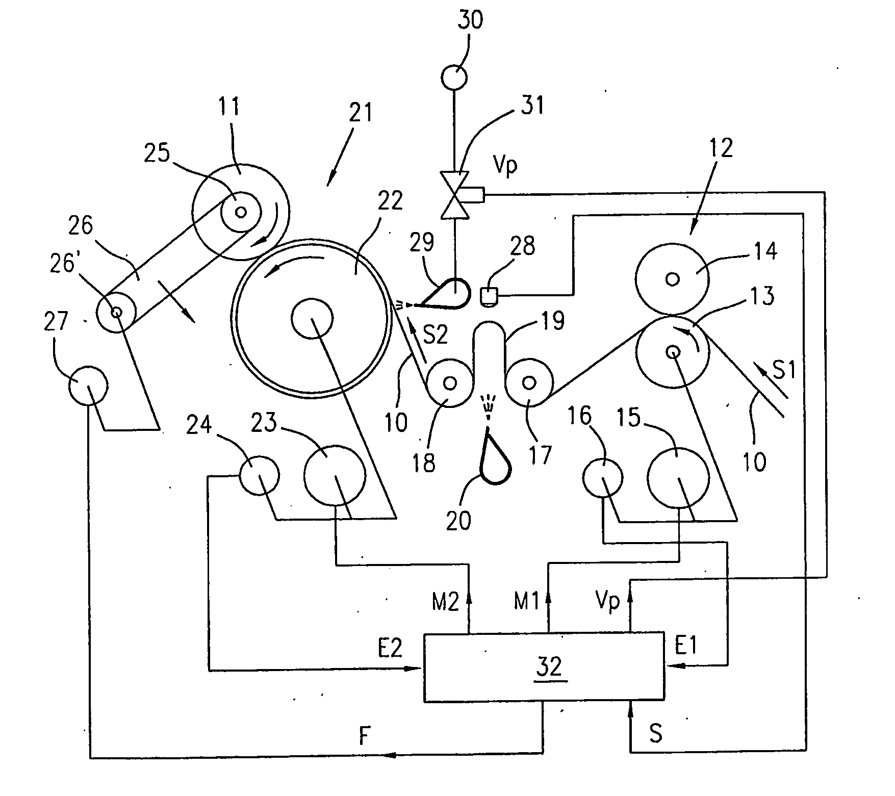
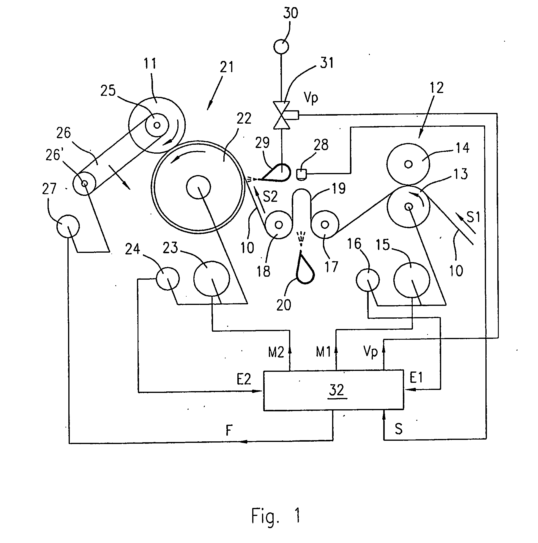
[0045]As shown in FIG. 1, reference number 10 indicates a film of plastic, paper or other material, which is unwound from a roll, not shown, to be embossed and rolled up or wound onto a spindle 25, to form a coreless or soft-core roll 11.

[0046]The film 10, which can be of any type, for example unrolled from large-sized rolls, or directly from a production line, is made to advance along an embossing path at a first feeding speed S1 by means of a feeding device 12 comprising a drawing roller 13 and a pressure roller 14.

[0047]The drawing roller 13 is operatively connected to a first electric motor 15 provided with a first signal generator 16, consisting for example of an incremental encoder.

[0048]Subsequently to the first drawing unit 12, the film 10 is deviated by two idle guide rollers 17 and...

second embodiment

[0074]FIG. 5 of the drawings shows the apparatus, which differs from the previous one in respect to the system for forming the loop 19, and for maintaining the film 10 in an unstressed condition; therefore in FIG. 5 the same reference numbers have been used to indicate parts similar or equivalent to those of FIG. 1.

[0075]The embodiment of FIG. 5 differs from that of FIG. 1 in that the loop 19 is now directed with the bottom facing downwards, and is formed immediately downstream of the feeding device 12, between the latter and the first guide roller 17; moreover, the same nozzle 20 also is now facing downwards, while the sensor 28 has been positioned beneath the loop 19.

[0076]The apparatus of FIG. 5 operates exactly in the same way as the apparatus of FIG. 1.

third embodiment

[0077]A third embodiment is shown in FIGS. 6 and 7 of the drawings, in which the same reference numbers of the previous figures have been used for corresponding parts.

[0078]The embodiment of FIGS. 6 and 7 differs from the embodiments of FIGS. 1 and 5 in that the loop 19, downstream the feeding device, is provided by a pneumatically actuate devices 43 comprising a movable and adjustably supports idle roller 45.

[0079]As shown, the idle roller 45 is supported by an arm 46, which may pivot around an axis 47 coaxial to the shaft of the roll 13.

[0080]The pivotal movement of the arm 46 is adjustably performed by an actuator, for example by an air pressure actuated cylinder 48 hinged to the arm 46 and connected to an air pressure source 50 by a control valve 49 controlled by the outlet Vs of the control unit 33.

[0081]Position sensing means for the idle roller 45, such as linen encoder 51 are provided to control the position and / or the depth of the loop 16 as per previous cases.

[0082]An addi...


PUM

PropertyMeasurementUnit
thicknessaaaaaaaaaa
depthaaaaaaaaaa
feeding speedaaaaaaaaaa

Abstract

A method and an apparatus for winding coreless and soft-core rolls (11), of film materials (10). The film (10) is made to advance, at differentiate speeds (S1, S2), between a first and a second drawing unit (12, 21) making the film (10) to perform a floating loop (19). The film (10) is fed in a controlled way, making it adhere to a grooved embossing drum (22) by an air jet (29) to emboss cross corrugations in the film (10) while it is being wound up; the corrugations of the film (10) traps air and prevents the implosion of the roll (11). A programmable electronic unit (32), controls the drawing units (12, 21) in relation to control signals (E1, E2) related to the feeding and winding up speeds (S1, S2) of the film (10), and in relation to a control signal supplied by a sensing device (28) for detecting the position of the floating loop (19).

Description

BACKGROUND OF THE INVENTION[0001]This invention refers to the production of soft-core and coreless rolls of films or continuous band of thin sheet material such as stretchable and heat shrinkable plastic films, or bands in paper or different materials, which are continuously fed, embossed and wound or rolled up onto a spindle to form a roll in a controlled mode.[0002]More precisely, the invention relates to a method and an apparatus for producing soft-core and coreless rolls of a film material namely devoid of a support tube, or provided with a support soft tubular core for winding up the film. For the purpose of the present invention, “soft-core” means a core of soft or flexible material, such as paper and the like, for winding up the film, compared to rigid cardboard cores.[0003]The invention is also directed to a coreless or soft-core roll of film material obtained according to the claimed method.[0004]Although the formation of coreless or soft-core rolls for example of plastic f...

Claims


Application Information

Patent Timeline
Patent Type & Authority Applications(United States)
IPC IPC(8): B65H18/16B65H23/00B65H59/38B29C59/04B65H20/24B65H23/04
CPCB65H18/16B65H20/24B65H23/042
Inventor PELLENGO GATTI, ROBERTO
Owner NOEL
Why Eureka
Try Eureka