Method, system, and machine to track and anticipate the movement of fluid spills when moving with water flow

a technology of fluid spill detection and movement, applied in the field of real-time tracking systems, can solve the problems that the previous spill tracking systems had limited value beyond the fluid spill tracking field, and achieve the effects of enhancing emergency preparedness and decision-making capabilities, accurate measurement and mapping, and saving time, resources and most importantly, lives

Inactive Publication Date: 2013-03-14
SAUDI ARABIAN OIL CO
View PDF1 Cites 45 Cited by
  • Summary
  • Abstract
  • Description
  • Claims
  • Application Information

AI Technical Summary

Benefits of technology

[0012]The system, machine, and method of the current application provides a new, low-cost tool for emergency responders to accurately measure and map the actual movement of sea currents or fluid slicks regardless of weather, sea-state, or visibility. Embodiments of the invention enhance both the emergency preparedness and decision making capabilities of those who work in a marine environment by allowing emergency responders and management to see the exact location and behavior of the fluid slick and rapidly plan strong contingency measures such as sea water intake protection. In some embodiments, the solution utilizes low-cost, ruggedized, simple tracking devices, which can be integrated with a company's existing enterprise information technology systems.
[0013]The previous spill tracking systems had limited value beyond fluid spill tracking due to the size, weight and cost of the tracking devices. However, in addition to 24 hour tracking of fluid slicks, embodiments of the invention have potential uses in marine search and rescue operations. For example, during a man overboard event, one of the devices / tools could be deployed in the immediate vicinity of the person's last position (e.g. an offshore platform or sinking vessel). In this example, the device would transmit the actual sea currents in a local offshore area, enabling geographic information systems (GIS) displays to be generated that accurately depict the local sea currents and focus rescue resources down current. The improved GIS maps displays could potentially save time, resources, and most importantly—lives.
[0014]Embodiments of the invention could also be used to track emergency life rafts stationed at offshore oil and gas processing facilities. In this case, the tracking device would serve as a low-cost and effective locator beacon in the event of the raft being deployed.
[0015]Beyond the safety applications, embodiments of the invention could provide marine supervisors and planners with an accurate overview of portable offshore assets and operations. For example, the system could be used to mark the location of under-sea dive crews doing underwater welding at an offshore pipeline or platform. In this example, providing a unified map-based view of all diving operations would encourage optimization of resources, and could also improve health and safety by improving awareness of where the crews are operating.
[0016]In alternative applications of some embodiments of the invention, accurate, local sea current data could be economically collected. Using live sea surface current data would dramatically improve the accuracy of fluid spill trajectory models and help drive more accurate decisions and contingency plans. For example, the tracking devices could be deployed into the sea during emergency drills to simulate a moving fluid spill or a man overboard event. In this example, GIS maps displays generated based on live data would improve the realism of offshore drills and would also enable the fluid spill trajectory models or sea surface mapping models to be scrutinized during an integrated scenario.
[0017]Data collected with embodiments of the present invention could also support the design of marine engineering projects such as shoreline protection, upgrading sea-water intakes, or dredging of sea channels or ports. For example, by monitoring a number of tracking devices, accurate sea-current data could be collected across any project area on several dates to reduce seasonal weather factors. Such data is expensive to collect using conventional approaches.

Problems solved by technology

The previous spill tracking systems had limited value beyond fluid spill tracking due to the size, weight and cost of the tracking devices.

Method used


Image

  • Method, system, and machine to track and anticipate the movement of fluid spills when moving with water flow
  • Method, system, and machine to track and anticipate the movement of fluid spills when moving with water flow
  • Method, system, and machine to track and anticipate the movement of fluid spills when moving with water flow

Examples


Embodiment Construction

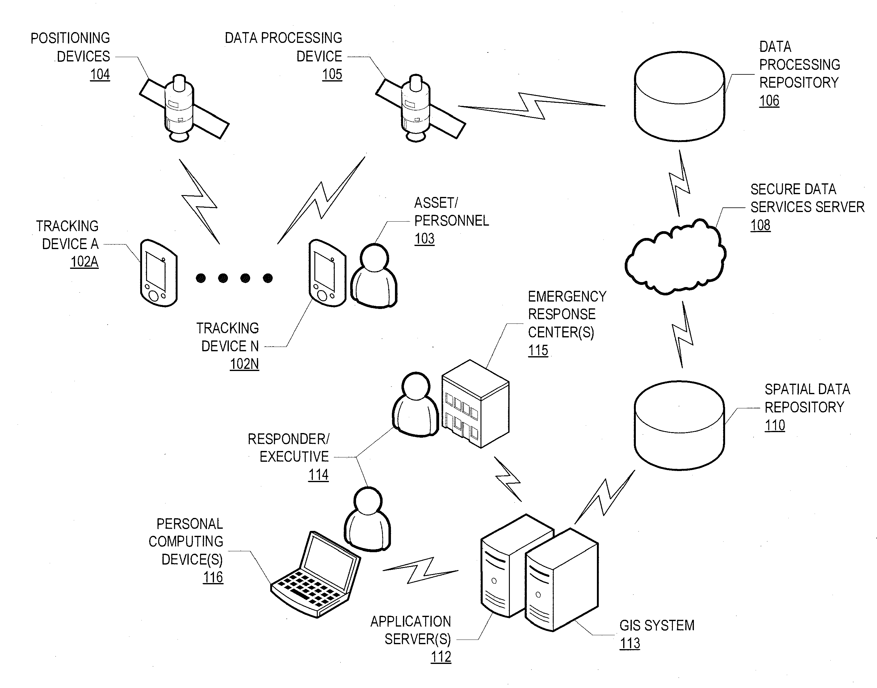
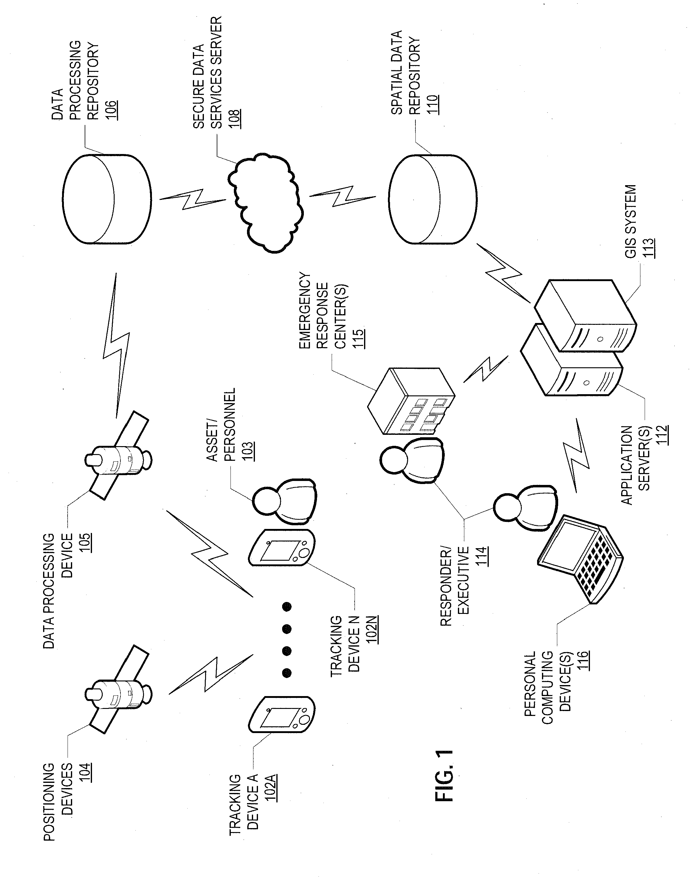
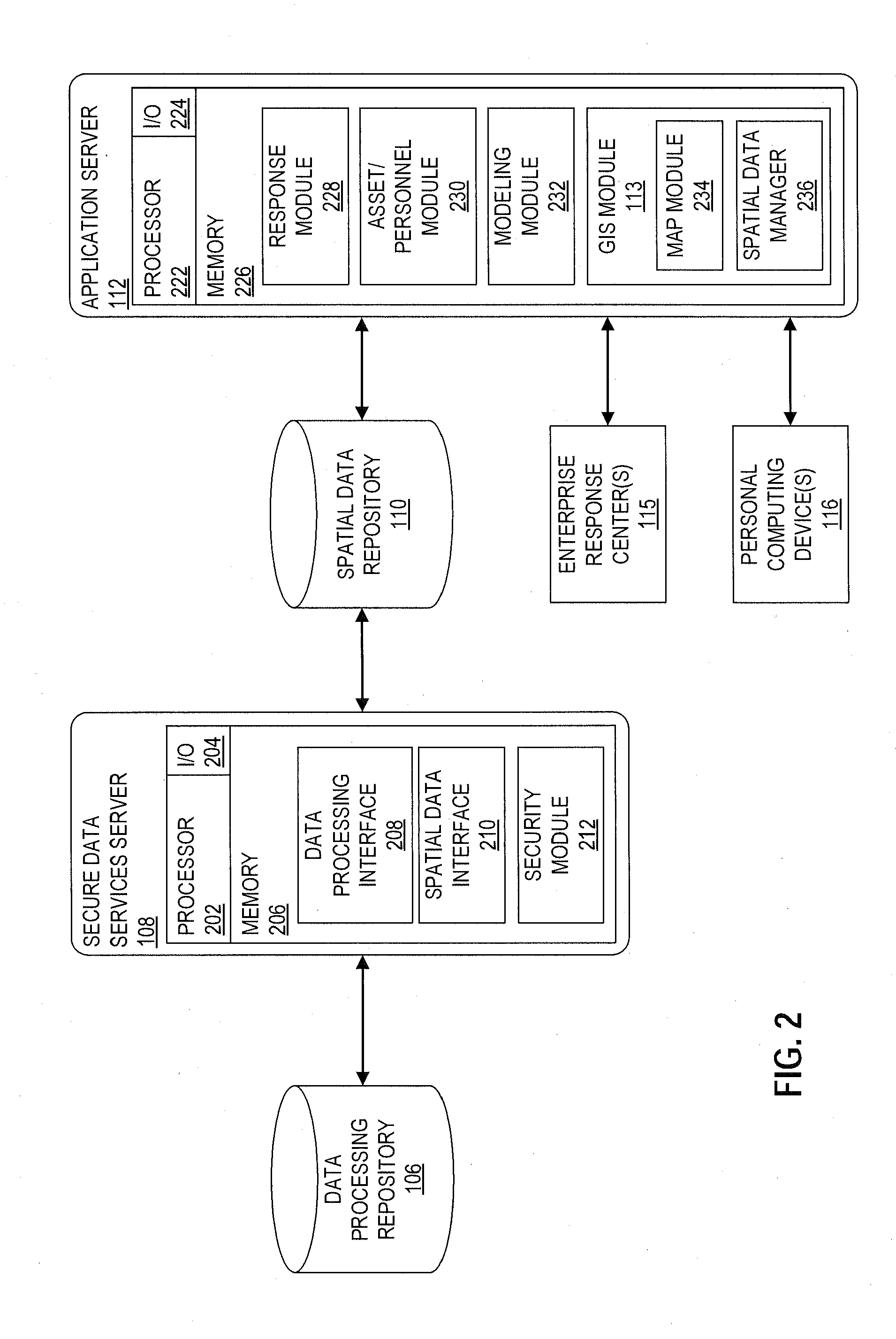
[0028]As discussed in more detail below, provided in some embodiments are systems and methods for actively tracking movement using low-cost tracking devices, which can be useful for emergency response planning, tactical oil spill response planning, or other applications in which movement is tracked in a marine environment. In one embodiment, the method for tracking fluid spills when moving with a water flow includes the steps of obtaining location and movement data for each of a number of tracking devices from a positioning satellite data repository, the location data for each of the respective tracking devices including a device identifier, a geographic location and velocity (historical and current) of a tracking device, and a timestamp for each geographic location and velocity received. The method further includes integrating the location and velocity data of each of the tracking devices into a spatial data repository according to the device identifier, determining a deployment lo...


PUM


Abstract

The present invention relates to systems, methods, and machines for tracking a fluid spill. The method includes obtaining real-time location data for a number of tracking devices from a positioning satellite data repository, integrating the location data of each of the tracking devices into a comprehensive spatial data repository, determining a deployment location for each of the tracking devices, identifying, responsive to the deployment locations, a fluid-spill subset of the tracking devices that were deployed in the fluid spill, determining a fluid spill location based on the geographic locations of the fluid-spill subset, and generating a geographic map depicting the fluid spill location. A new sensor-driven paradigm is used that combines practical data gathering methods with advanced enterprise information technologies. The sensor-driven paradigm provides real-time situational awareness to emergency responders and executive stakeholders working from remote locations during an oil spill or chemical fluid release.

Description

CROSS REFERENCE TO RELATED APPLICATIONS[0001]This application claims the benefit of the filing date of U.S. Provisional Patent Application No. 61 / 478,823, attorney docket number 004159.007039, filed on Apr. 25, 2011, the disclosure of which is incorporated by reference herein in its entirety.[0002]This application relates to co-pending U.S. Non-provisional patent application Ser. No. ______ attorney docket number 004159.007039, by O'Regan et al, titled “Method And Tracking Device for Tracking Movement in a Marine Environment,” filed on Apr. 24, 2012, the disclosure of which is incorporated by reference herein in its entirety.BACKGROUND OF THE INVENTION[0003]1. Field of the Invention[0004]Embodiments of the invention relate to systems, machines, and methods for tracking movement. More specifically, embodiments of the present invention relate to a real-time tracking system for processing location data from tracking devices deployed in a marine environment.[0005]2. Description of the R...

Claims


Application Information

Patent Timeline
Patent Type & Authority Applications(United States)
IPC IPC(8): G01S19/42G01S19/17
CPCE02B15/00G01S19/14G01S5/0027
Inventor O'REGAN, PETER R.ALMOHSEN, ALI AMER
Owner SAUDI ARABIAN OIL CO
Why Eureka
Try Eureka