
Compression type coaxial cable connector

Active Publication Date: 2013-03-14
HOLLAND ELECTRONICS
View PDF13 Cites 3 Cited by
  • Summary
  • Abstract
  • Description
  • Claims
  • Application Information

AI Technical Summary

Benefits of technology

This patent is about an electrical signal connector that is used with coaxial cables. It has a cylindrical casing and a slidable barrel, which is like a cylindrical shell. The connector has several improvements, including easy operation, a compact design, no plug or cap at the end, and a single tool for compression. The tool doesn't need to be mounted at the end of the connector.

Problems solved by technology

Due to critical requirements from consumers, signal transmission requires high stability and rapid speed.
This installation procedure is complicated, requiring much effort.
Further, if the outer tubular member A3 is biased relative to the coaxial cable B and the barbed portion A31 of the outer tubular member A3 is not positively forced into engagement with the braided metal wrapper (woven copper shield) B4 and outer plastic sheath B5 of the coaxial cable B against the inner tubular member A2, the signal transmission quality will be adversely affected.

Method used


Image

  • Compression type coaxial cable connector
  • Compression type coaxial cable connector
  • Compression type coaxial cable connector

Examples


Embodiment Construction

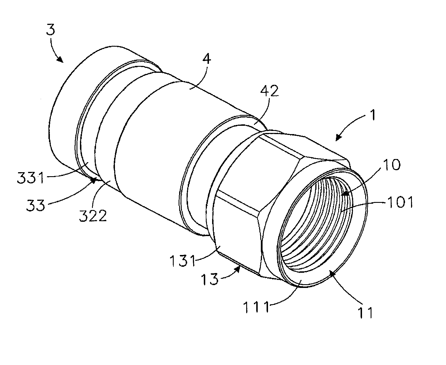
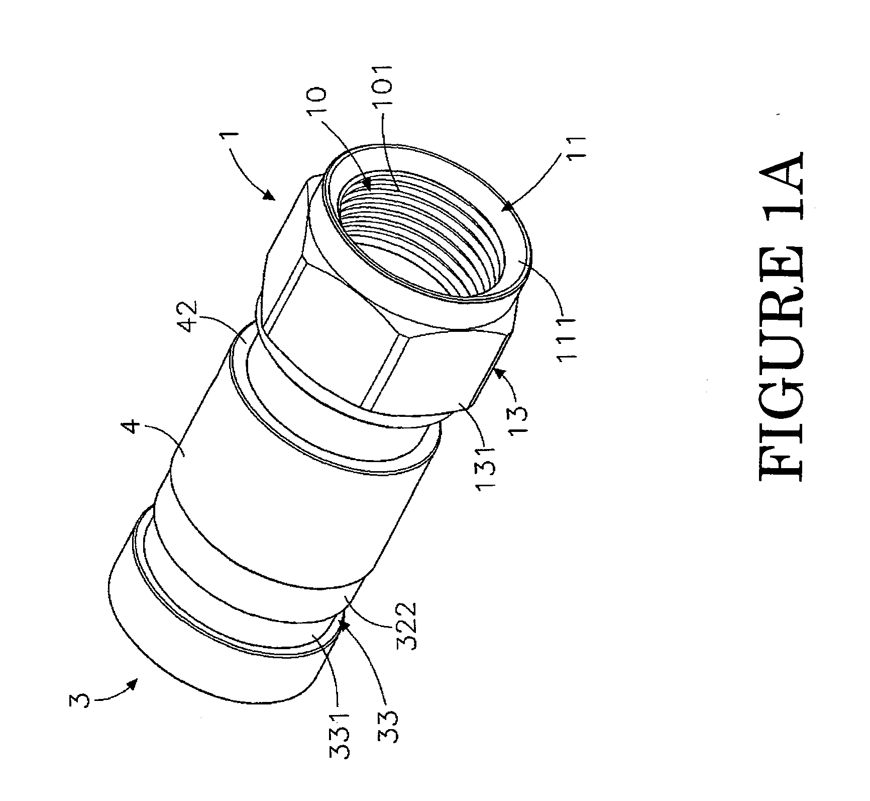
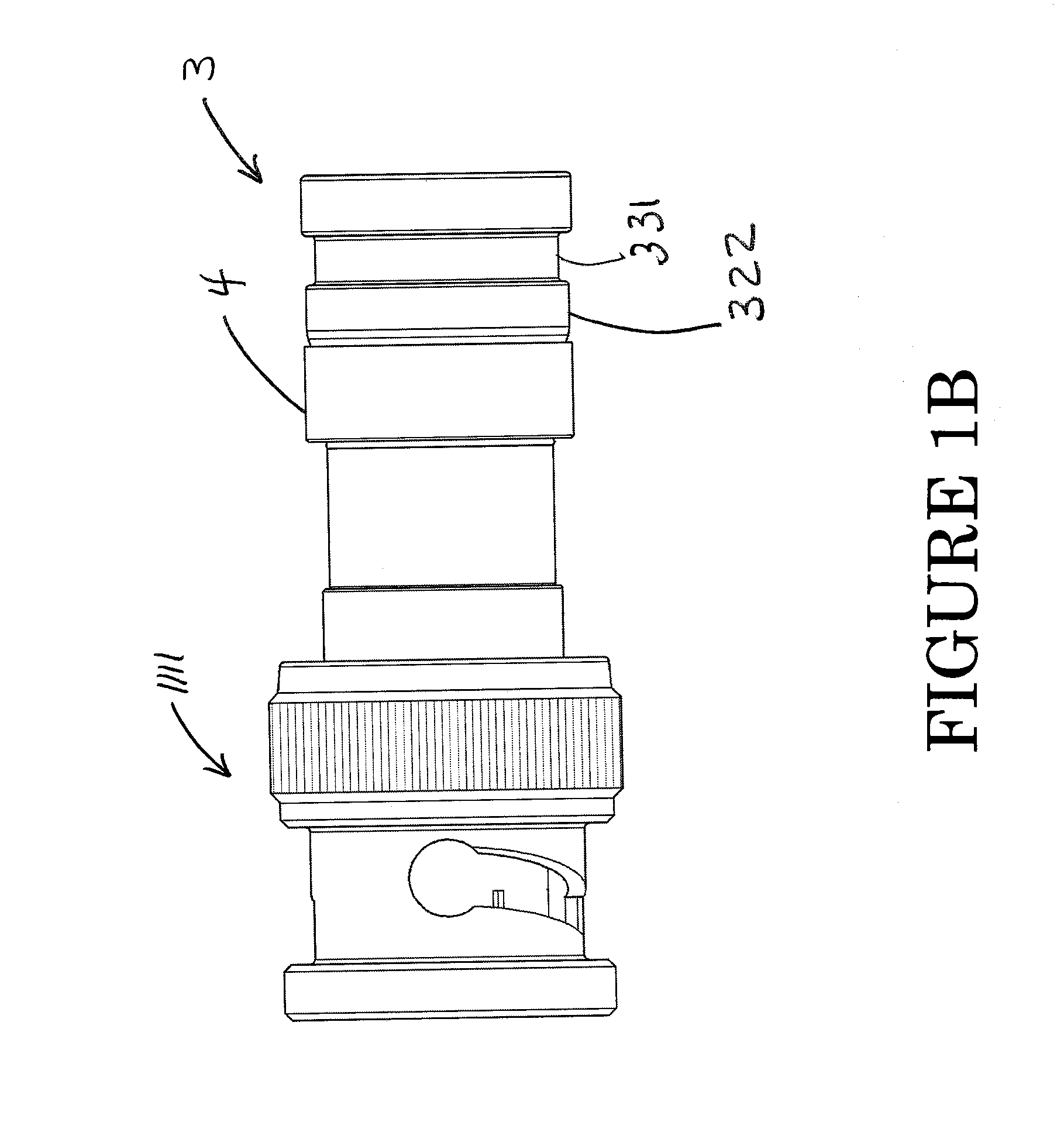
[0037]Referring to FIGS. 1A-C, 2, 3, and 4A, embodiments of the electrical signal connector of the present invention are shown. The electrical signal connector comprises a core tube 2, a cylindrical casing 3 and a barrel 4. An optional fastener (1, 1111, 1112), for example a fastener in the form of an internally threaded locknut 1 is also shown. Variants of this fastener include any of F-Type, BNC, RCA, and other suitable coaxial cable connector fasteners known to persons of ordinary skill in the art. See for example the BNC connector embodiment of FIG. 1B and the RCA connector embodiment of FIG. 1C. Unless otherwise noted, an F-Type connector such as the connector of FIG. 1A is used to illustrate features of the invention. As used herein, cylindrical includes enveloping shapes such as cylinders, polygons, and irregular enveloping shapes. And, as used herein, barrel includes sleeve-like structures such as a barrel having one or more cylindrical inner diameters and one or more cylind...


PUM

PropertyMeasurementUnit
Thicknessaaaaaaaaaa
Deformation enthalpyaaaaaaaaaa

Abstract

An electrical connector for use with coaxial cables includes a deformable cylindrical casing and a slidably engaged shell.

Description

PRIORITY CLAIM[0001]This application claims the benefit of provisional patent application No. 61 / 534,337 filed Sep. 13, 2011 and titled ELECTRICAL SIGNAL CONNECTOR.BACKGROUND OF THE INVENTION[0002]1. Field of the Invention[0003]The present invention relates to items of manufacture. More particularly, the present invention relates to a signal connector useful for, among other things, terminating a signal cable.[0004]2. Description of the Related Art[0005]Following the fast development of electronic and multimedia technology, advanced TV, audio system, video player, digital camera, video game machine and many other electronic products have been continuously created to serve people. Due to critical requirements from consumers, signal transmission requires high stability and rapid speed. To achieve high performance, high quality audio and video equipment must be used with high quality signal lines and signal connectors.[0006]Subject to the application of telephone technology, video tech...

Claims


Application Information

Patent Timeline
IPC IPC(8): H01R9/05H01R43/20
CPCH01R13/502H01R9/0524Y10T29/49208
Inventor HOLLAND, MICHAEL
Owner HOLLAND ELECTRONICS
Learn More