Method of making eyeglass frame by injection molding

a technology of injection molding and eyeglass frames, which is applied in the direction of instruments, coatings, non-optical parts, etc., can solve the problems of large amount of plastic waste, low resolution, and design patterns produced by current technologies, and achieves the effects of reducing plastic waste and thus costs, simple and simpl

Inactive Publication Date: 2013-03-21
OKIA OPTICAL
View PDF5 Cites 36 Cited by
  • Summary
  • Abstract
  • Description
  • Claims
  • Application Information

AI Technical Summary

Benefits of technology

[0006]Provided herein are methods of making eyeglass frames with a significant reduction in plastic waste and thus costs during the manufacturing of the eyeglass frames. Also provided herein are methods of making eyeglass frames that are simple and inexpensive. Also provided herein are methods of making eyeglass frames that produce any desirable high-definition images and design patterns that are durable. In some embodiments, the methods comprise making eyeglass frames comprising a frame front and / or a pair of temples having a high-definition design pattern by injection molding.

Problems solved by technology

Such operations generate a large amount of plastic waste, especially during blanking where the bulk of the waste is in the form of the lens portion of the frame.
However, design patterns produced by the current technologies, e.g., silk screen printing or injection molding with design patterns printed on an outer surface of the molded article, have low resolution.
Another drawback of silk screen printing is that it requires different screens for different patterns.
However, the protecting layer and thus the pattern layer are generally not durable and can be worn down over time and become unappealing.
As a result, the current technologies not only have poor resolution or quality, but also are complex and expensive, and / or produces images and design patterns which are undurable.

Method used


Image

  • Method of making eyeglass frame by injection molding
  • Method of making eyeglass frame by injection molding
  • Method of making eyeglass frame by injection molding

Examples


example 1

Making an Eyeglass Temple Having a Two-Layer Structure with a Design Pattern

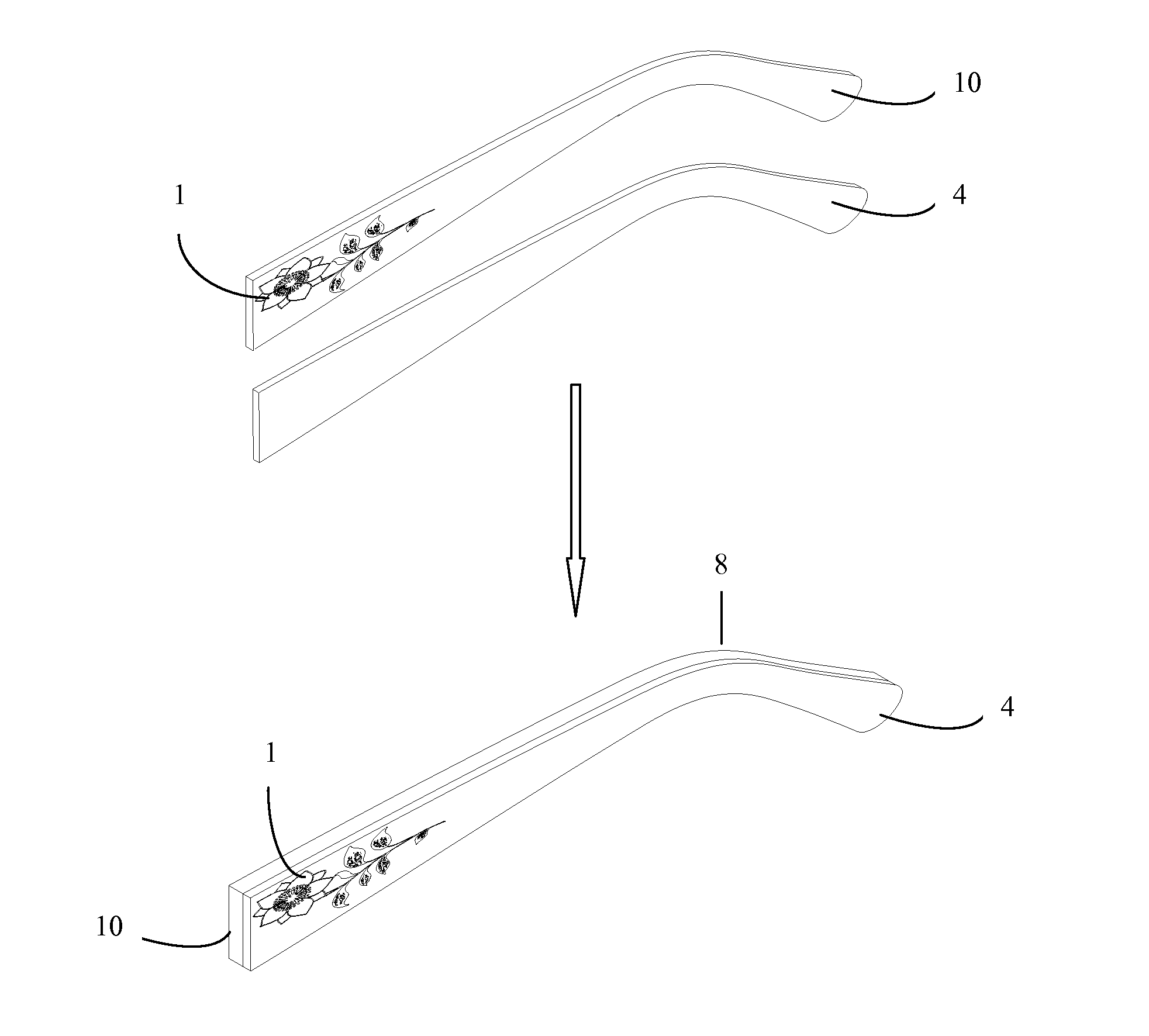
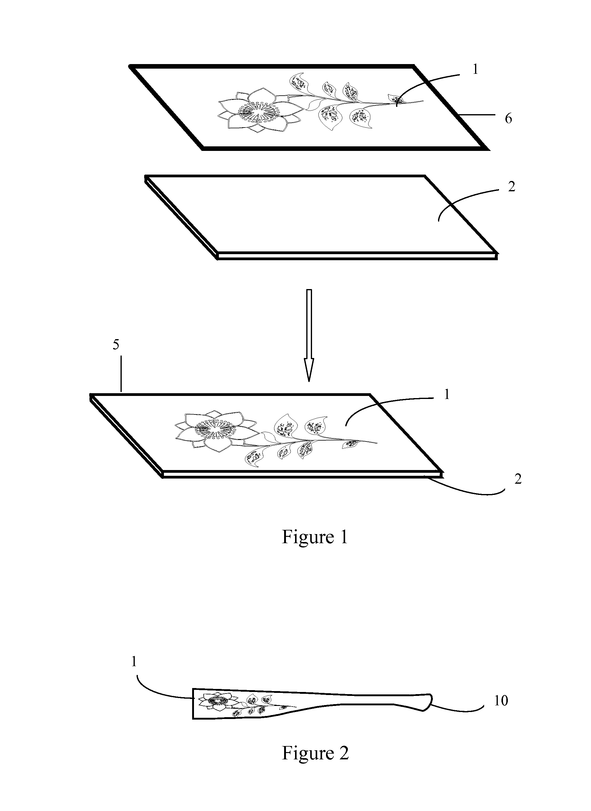
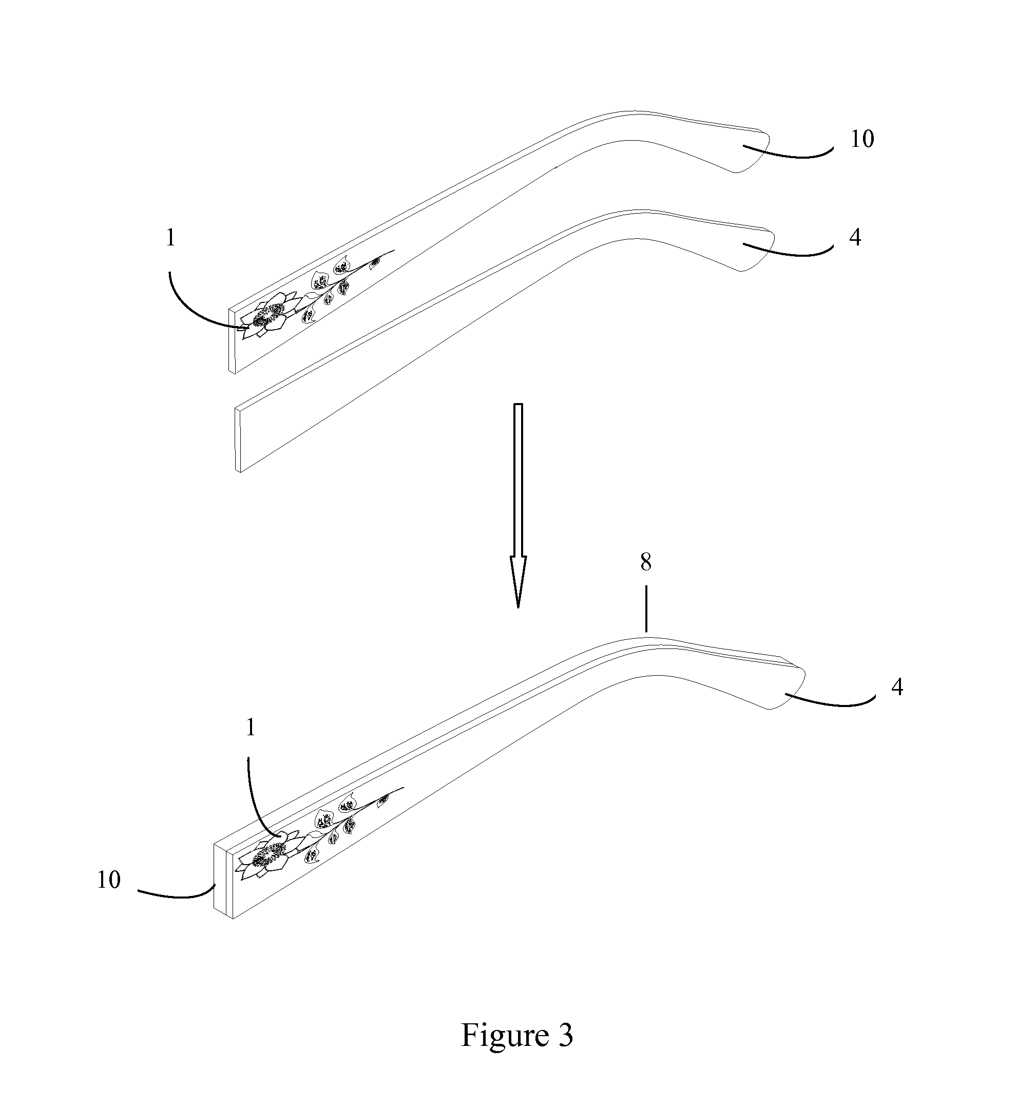
[0139]A design pattern (1) was first designed with a computer. The design pattern (1) was printed on a transfer sheet (6) by using a printer with sublimation inks wherein the humidity during the printing process was from about 45% to about 80%. The design pattern (1) was then printed from the transfer sheet (6) to a surface of a laminate (2) by heat press transfer printing to form a patterned laminate (5) as shown in FIG. 1 (the heat press was not shown). The transfer temperature was from about 150° C. to about 200° C. and the transfer time was from about 30 seconds to about 200 seconds. The laminate (2) with the design pattern (1) was converted into a patterned layer (10) having the shape of a temple as shown in FIG. 2. The patterned layer (10) was coated with JP-202, a lamination agent comprising triethyl citrate and cyclohexanone. Referring to FIG. 3, the patterned layer (10) was set in the cavity of a mo...

example 2

Making an Eyeglass Temple Having a Three-Layer Structure with a Design Pattern

[0140]A design pattern (1) was first designed with a computer. The design pattern (1) was printed on a transfer sheet (6) by using a printer with sublimation inks wherein the humidity during the printing process was from about 45% to about 80%. The design pattern (1) was then printed from the transfer sheet (6) to a surface of a laminate (2) by heat press transfer printing to form a patterned laminate (5) as shown in FIG. 1 (the heat press was not shown). The transfer temperature was from about 150° C. to about 200° C. and the transfer time was from about 30 seconds to about 200 seconds. The laminate (2) with the design pattern (1) was converted into a patterned layer (10) having the shape of a temple as shown in FIG. 2. The patterned layer (10) was coated with JP-202, a lamination agent. Referring to FIG. 4, the patterned layer (10) was set in the cavity of a mold of the injection molding machine (not sho...

example 3

Making an Eyeglass Temple Having a Two-Layer Structure with a Design Pattern and a Metal Logo

[0142]A design pattern (11) was first designed with a computer. The design pattern (11) was printed on a transfer sheet (16) by using a printer with sublimation inks wherein the humidity during the printing process was from about 45% to about 80%. The design pattern (11) was then printed from the transfer sheet (16) to a laminate (12) by heat press transfer printing to form a patterned laminate (13) as shown in FIG. 5 (the heat press was not shown). The transfer temperature was from about 150° C. to about 200° C. and the transfer time was from about 30 seconds to about 200 seconds. Referring to FIG. 6, a metal logo (15) was placed on top of the patterned laminate (13). The patterned laminate (13) with the design pattern (11) and metal logo (15) was converted into a patterned layer (20) having the shape of a temple as shown in FIG. 6. The patterned layer (20) was coated with JP-202, a laminat...


PUM

PropertyMeasurementUnit
transfer temperatureaaaaaaaaaa
mold pressureaaaaaaaaaa
mold temperatureaaaaaaaaaa

Abstract

Disclosed herein are methods of making an eyeglass frame comprising a frame front and/or a pair of temples, wherein each of the frame front and temples independently comprises a top layer and a patterned layer having the shape of a frame front and/or a pair of temples, and wherein the patterned layer comprises a laminate and a design pattern on a surface of the laminate, the method comprising the steps of: a) providing a mold having a cavity, wherein the shape of the cavity corresponds to the shape of the frame front and/or the temples; b) setting the patterned layer for the frame front and/or the temples in the mold; and c) injecting a melt of a first polymer composition into the cavity to form the top layer. In some embodiments, at least one of the frame front and temples further comprises a bottom layer.

Description

FIELD OF THE INVENTION[0001]This invention relates to methods of making eyeglass frames by molding techniques, in particular, making eyeglass frames comprising a frame front and / or temples having a design pattern by injection molding. In some embodiments, the design pattern comprises one or more high-definition images.BACKGROUND OF THE INVENTION[0002]Eyeglasses (aka glasses or spectacles) generally can be used for vision correction and / or eye protection from hazards such as UV light or sunlight. Modern eyeglasses generally comprise a pair of lenses mounted on an eyeglass frame which can be worn in front of the wearer's eyes. The eyeglass frame may be supported by pads on the bridge of the nose and / or by temples placed over the ears.[0003]Eyeglass frames, which may comprise a frame front and / or temples, are generally made from plastic sheets, such as sheets of cellulose acetate, by die-cutting at a temperature at or above its softening point. In general, the softened plastic sheets a...

Claims


Application Information

Patent Timeline
Patent Type & Authority Applications(United States)
IPC IPC(8): B29C45/14
CPCB29K2995/0074B29L2012/005B29C45/14688B29C2045/14721B29C45/1671G02C5/008B29C2045/14237B29C45/14811B29D12/02
Inventor ZHANG, YANLAM, YIN SANG
Owner OKIA OPTICAL
Why Eureka
Try Eureka