Magnetic resonance imaging apparatus and high-frequency magnetic field pulse modulation method

a high-frequency magnetic field and pulse modulation technology, applied in the field of magnetic resonance imaging apparatus, can solve the problem that the response of the slice gradient magnetic field that is actually applied is not necessarily an ideal slice gradient magnetic field response, and achieve the effect of good image quality and no artifacts

Inactive Publication Date: 2013-03-21
HITACHI MEDICAL CORP
View PDF10 Cites 9 Cited by
  • Summary
  • Abstract
  • Description
  • Claims
  • Application Information

AI Technical Summary

Benefits of technology

[0020]Advantageous Effects of Invention
[0021]According to the MRI apparatus of the present invention, an actual gradient magnetic field response is measured immediately before imaging, and a high frequency magnetic field pulse is modulated using the measurement data. Therefor...

Problems solved by technology

However, the response of the slice gradient magnetic field that is actua...

Method used


Image

  • Magnetic resonance imaging apparatus and high-frequency magnetic field pulse modulation method
  • Magnetic resonance imaging apparatus and high-frequency magnetic field pulse modulation method
  • Magnetic resonance imaging apparatus and high-frequency magnetic field pulse modulation method

Examples


first embodiment

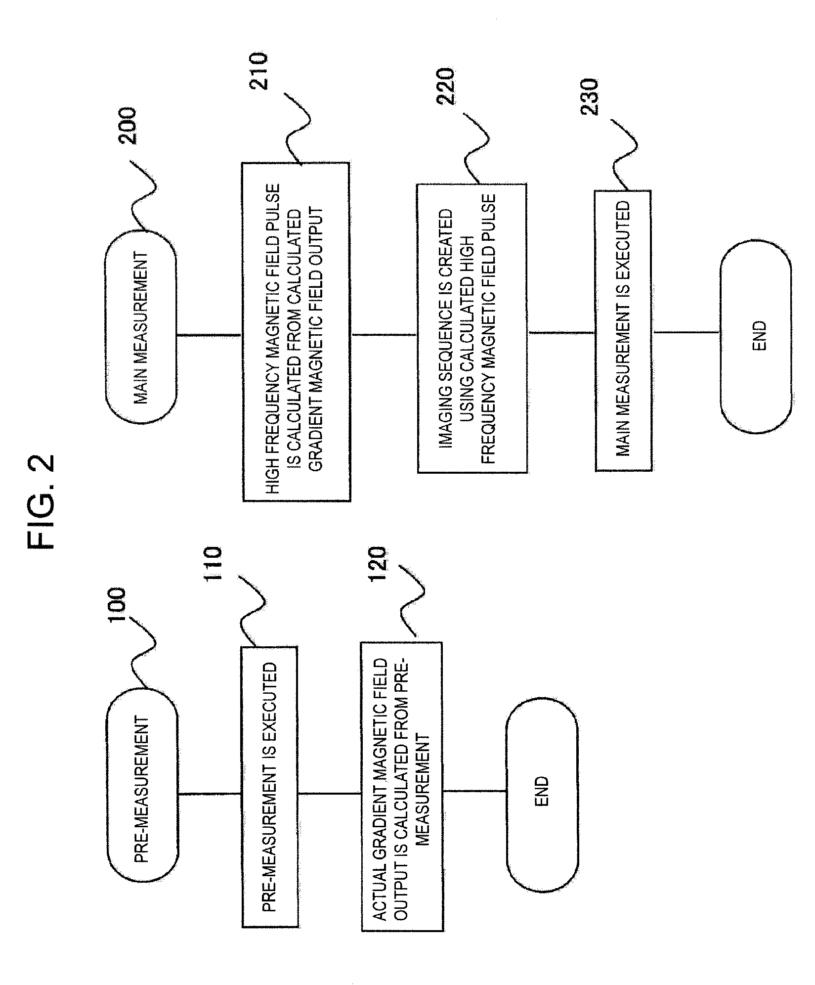
[0039]FIG. 2 shows an operation procedure of the present embodiment, and FIG. 3 shows a pulse sequence according to the present embodiment.

[0040]As shown in FIG. 2, imaging of the present embodiment includes pre-measurement 100 for measuring a gradient magnetic field pulse and main measurement 200 using the RE pulse shape determined from the result of the pre-measurement.

[0041]The pre-measurement 100 is measurement for calculating the output of the slice gradient magnetic field applied in the same conditions as the slice gradient magnetic field used in the main measurement 200, and includes a step 110 of executing a pre-measurement pulse sequence 310 and a subsequent step 120 of calculating the gradient magnetic field output (response of the actual gradient magnetic field) that are shown in FIG. 3. In the present embodiment, the main measurement 200 is measurement based on the UTE imaging sequence, and includes a step 210 of calculating the RF pulse using the gradient magnetic field...

second embodiment

[0071]Next, an embodiment in which the present invention is applied to an MRI apparatus that performs imaging continuously while changing the conditions of slice selection will be described. Examples of continuous imaging, which is an object of the present invention, include dynamic imaging in which imaging is performed while changing the slice section or the imaging conditions interactively according to the behavior of the object, such as bending motion of the joint, imaging of switching from 3D imaging to 2D imaging, or the like.

[0072]FIG. 9 shows an imaging procedure of the present embodiment. Also in the present embodiment, in order that the shape of the RF pulse used in main measurement is determined in advance of the main measurement, performing the pre-measurement of the response of the gradient magnetic field pulse is the same as in the first embodiment. That is, also in the present embodiment, the pulse sequence 310 in the pre-measurement shown in FIG. 3 is executed using t...


PUM


Abstract

Degradation of the slice excitation characteristics is prevented by making it possible to modulate a high frequency magnetic field pulse on the basis of a gradient magnetic field response that is actually used. In order to do so, an imaging pulse sequence including first and second measurement sequences is executed. In the first measurement sequence, the same slice selection gradient magnetic field pulse as a slice selection gradient magnetic field pulse used in the second measurement sequence is used. The phase of a magnetic resonance signal measured by the first measurement sequence is differentiated, and the waveform of the high frequency magnetic field pulse is calculated using the result. In the second measurement sequence, a high frequency magnetic field pulse with the calculated waveform is applied together with the slice selection gradient magnetic field pulse, and a magnetic resonance signal for an image is measured.

Description

TECHNICAL FIELD[0001]The present invention relates to a magnetic resonance imaging apparatus (hereinafter, referred to as an MRI apparatus) and in particular, to an MRI apparatus suitable for ultra-short echo time (UTE) imaging in which slice-selective excitation is performed using a high frequency pulse with a half waveform and the signal is measured within the UTE.BACKGROUND ART[0002]In the MRI apparatus, when generating a nuclear magnetic resonance signal by exciting the nuclear spins of the object, a slice selection gradient magnetic field is applied together with a high frequency magnetic field pulse in order to selectively excite a specific region. As the high frequency magnetic field pulse, a high frequency modulated by an envelope, such as a symmetric sinc function, is usually used. The profile obtained by a Fourier transform of the high frequency magnetic field modulated by the sinc function in a frequency direction is a rectangle, and a predetermined rectangular region det...

Claims


Application Information

Patent Timeline
IPC IPC(8): G01R33/565G01R33/34
CPCG01R33/4833G01R33/4816G01R33/565G01R33/34
Inventor ABE, TAKAYUKI
Owner HITACHI MEDICAL CORP
Why Eureka
Try Eureka