Antenna structure for reducing the SAR value

a technology of antenna structure and sar value, which is applied in the direction of antenna coupling, antenna details, antennas, etc., can solve the problems of reducing the sar value effectively to less than 1.6 mw/g, and the cost of manufacturing the whole system is great, so as to reduce the sar value

Inactive Publication Date: 2013-03-21
AUDEN TECHNO
View PDF6 Cites 3 Cited by
  • Summary
  • Abstract
  • Description
  • Claims
  • Application Information

AI Technical Summary

Benefits of technology

[0005]One aspect of the instant disclosure relates to an antenna structure disposed inside an external casing according to an optimum separation distance for reducing the SAR value
[0006]One of the embodiments of the instant disclosure provides an antenna structure disposed inside an external casing according to an optimum separation distance for reducing the SAR value, comprising: a substrate unit and an antenna unit. The substrate unit includes at least one substrate body. The antenna unit includes at least one antenna layer disposed on the at least one substrate body, wherein the at least one antenna layer is extended along an X-axis direction to form an X-axis distance and is extended along a Y-axis direction to form a Y-axis distance, the X-axis direction is vertical to the Y-axis direction, and the X-axis distance of the at least one antenna layer is larger than the Y-axis distance of the at least one antenna layer. In addition, the optimum separation distance is defined from one end of the at least one antenna layer to the external surface of the external casing along the X-axis direction, and the optimum separation distance is substantially between 5 mm and 20 mm.
[0007]Another one of the embodiments of the instant disclosure provides an antenna structure disposed inside an external casing according to an optimum separation distance for reducing the SAR value, comprising: a substrate unit and an antenna unit. The substrate unit includes at least one substrate body. The antenna unit including at least one antenna layer disposed on the at least one substrate body, wherein the at least one antenna layer is extended along an X-axis direction to form an X-axis distance and is extended along a Y-axis direction to form a Y-axis distance, the X-axis direction is vertical to the Y-axis direction, and the X-axis distance of the at least one antenna layer is smaller than the Y-axis distance of the at least one antenna layer. In addition, the optimum separation distance is defined from one end of the at least one antenna layer to the external surface of the external casing along the Y-axis direction, and the optimum separation distance is substantially between 5 mm and 20 mm.
[0008]Therefore, the optimum separation distance defined from one end of the at least one antenna layer to the external surface of the external casing along the X-axis direction is substantially between 5 mm and 20 mm, and the optimum separation distance defined from one end of the at least one antenna layer to the external surface of the external casing along the Y-axis direction is substantially between 5 mm and 20 mm, thus the instant disclosure can obtain the SAR value less than 1.6 mW / g in high or low frequency operation according to the test site close to the external casing for testing the SAR value of the antenna structure.
[0009]To further understand the techniques, means and effects of the instant disclosure applied for achieving the prescribed objectives, the following detailed descriptions and appended drawings are hereby referred, such that, through which, the purposes, features and aspects of the instant disclosure can be thoroughly and concretely appreciated. However, the appended drawings are provided solely for reference and illustration, without any intention to limit the instant disclosure.

Problems solved by technology

Furthermore, how the antenna is configured in the system will have a great effect on the cost of manufacturing the whole system.
However, although the Federal Communication Committee (FCC) of USA prescribes that the permissible electromagnetic wave absorption rate (Specific Absorption Rate, SAR) shall not exceed 1.6 mW / g according to the four test sites (top, bottom, left, and right sides) close to the user of the notebook computer or the tablet computer, the SAR cannot be reduced effectively to less than 1.6 mW / g due to the limited space inside the notebook computer or the tablet computer.

Method used


Image

  • Antenna structure for reducing the SAR value
  • Antenna structure for reducing the SAR value
  • Antenna structure for reducing the SAR value

Examples


first embodiment

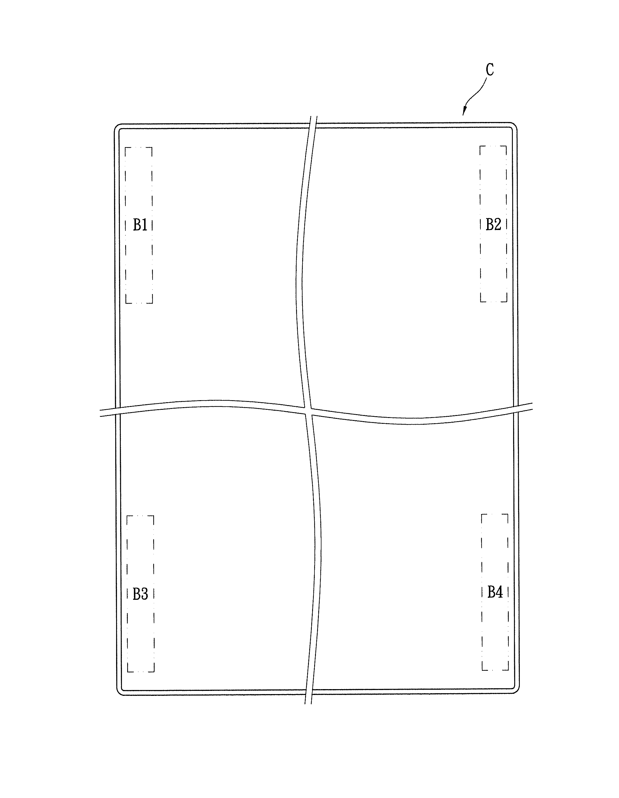
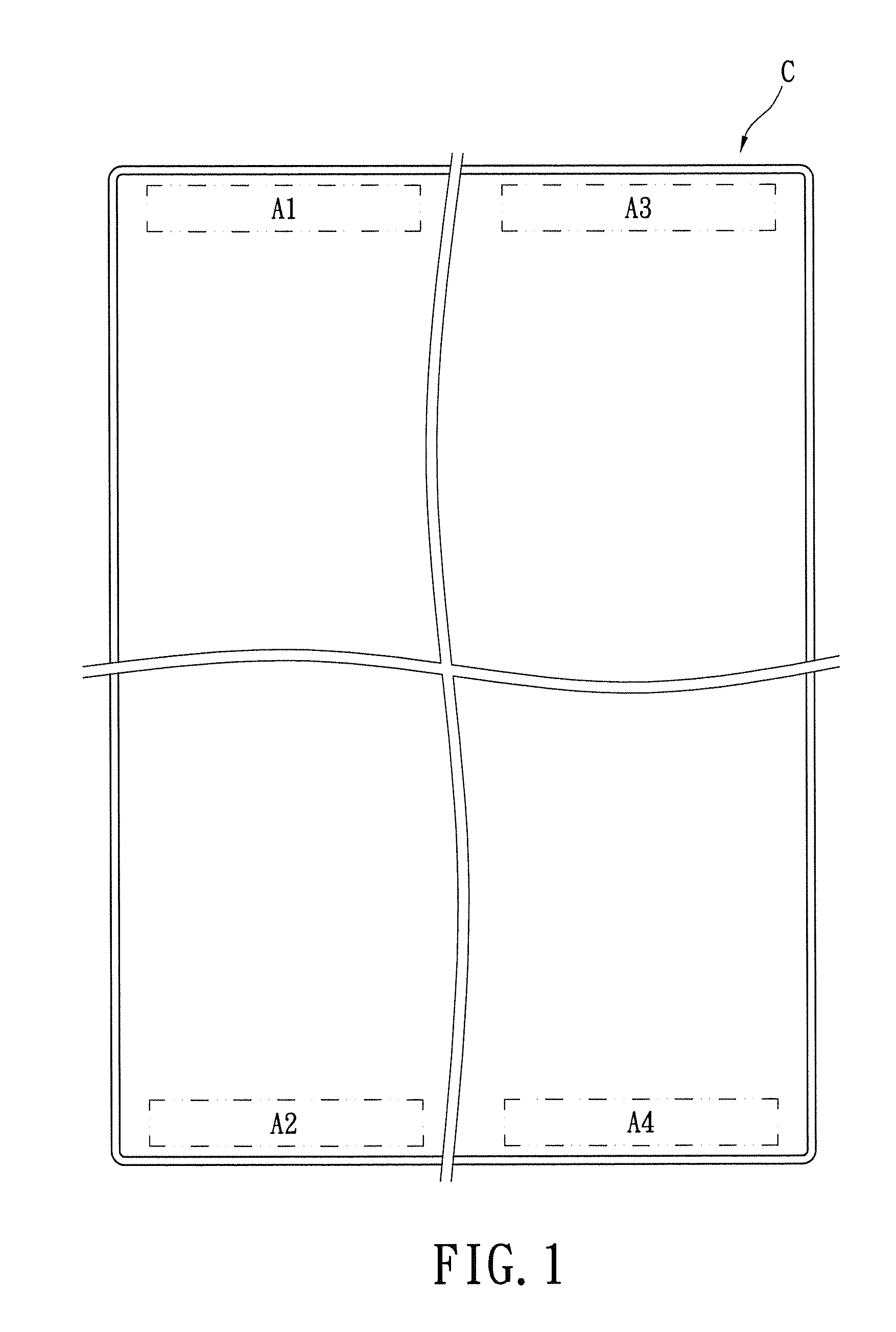
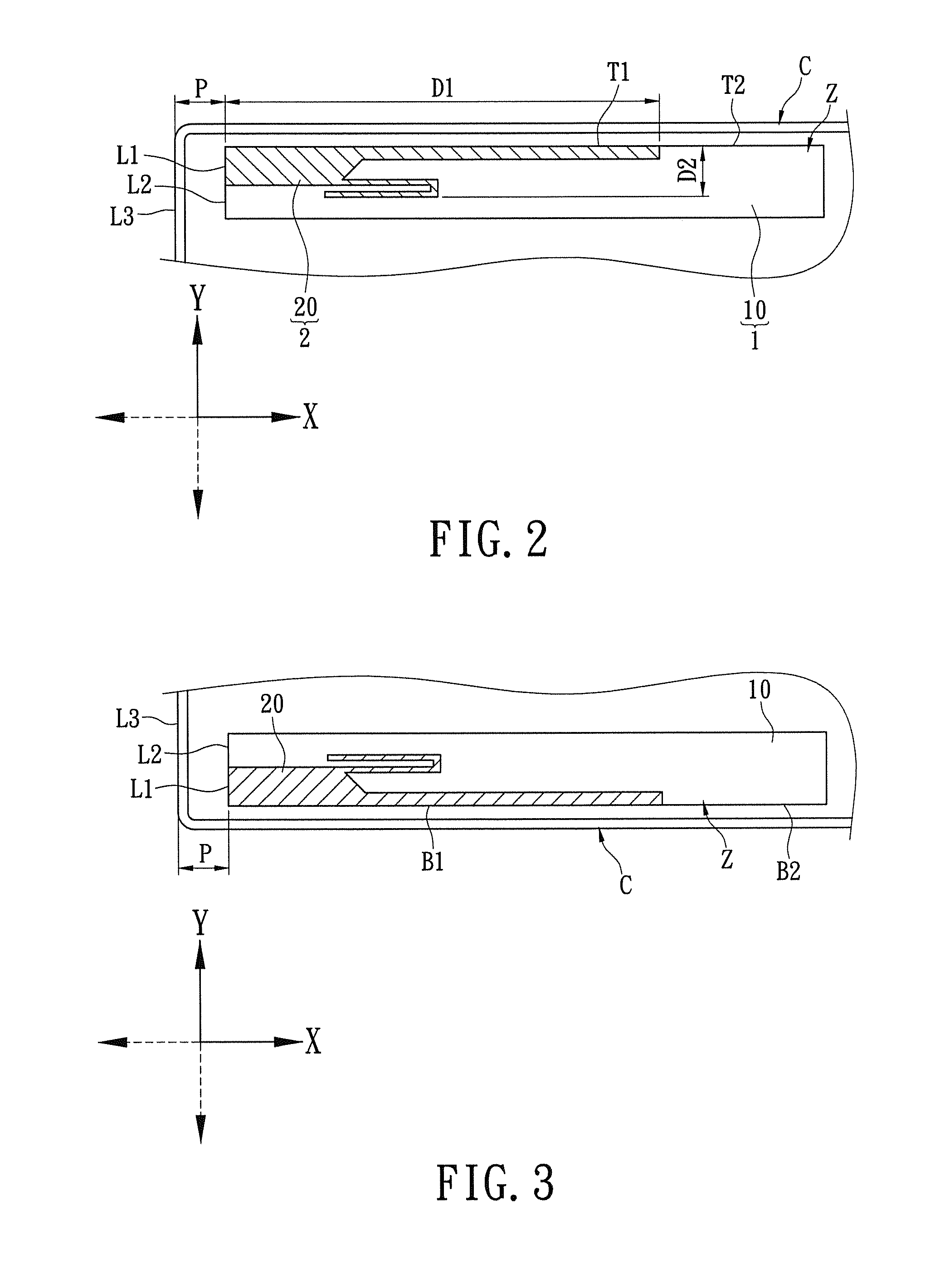
[0021]Referring to FIGS. 1 and 2, where the first embodiment of the instance disclosure provides an antenna structure Z disposed inside an external casing C (such as the casing of any electronic device) according to an optimum separation distance P for reducing the SAR value, and the antenna structure Z comprises a substrate unit 1 and an antenna unit 2. For example, the external casing C has a plurality of corner areas (A1, A2, A3 and A4 shown as the four phantom-line areas in FIG. 1) disposed in the external casing C and adjacent to the external surface of the external casing C, and the antenna structure Z can be disposed on one of the corner areas (A1, A2, A3 and A4) of the external casing C. For example, the antenna structure Z is disposed on the corner area A1 of the external casing C.

[0022]Referring to FIG. 2, the substrate unit 1 includes at least one substrate body 10. For example, the substrate body 10 may be a microwave substrate. However, the microwave substrate is merely...

second embodiment

[0025]Referring to FIGS. 1 and 3, where the second embodiment of the instance disclosure provides an antenna structure Z using an optimum separation distance P for reducing the SAR value. Comparing FIG. 3 with FIG. 2, the difference between the second embodiment and the first embodiment is that: the antenna structure Z of the second embodiment can be disposed on one corner area A2 of the external casing C. Moreover, the leftmost side L1 of the antenna layer 20 along the X-axis direction can be substantially flushed with the leftmost side L2 of the substrate body 10 along the X-axis direction, and the bottommost side B1 of the antenna layer 20 along the Y-axis direction can be substantially flushed with the bottommost side B2 of the substrate body 10 along the Y-axis direction. Of course, the optimum separation distance P also can be defined from the leftmost side L1 of the antenna layer 20 along the X-axis direction to the leftmost side L3 of the external casing C along the X-axis d...

third embodiment

[0026]Referring to FIGS. 1 and 4, where the third embodiment of the instance disclosure provides an antenna structure Z using an optimum separation distance P for reducing the SAR value. Comparing FIG. 4 with FIG. 2, the difference between the third embodiment and the first embodiment is that: the antenna structure Z of the second embodiment can be disposed on one corner area A3 of the external casing C. The optimum separation distance P can be defined from the rightmost side R1 of the antenna layer 20 along the X-axis direction to the rightmost side R3 of the external casing C along the X-axis direction. Moreover, the rightmost side R1 of the antenna layer 20 along the X-axis direction can be substantially flushed with the rightmost side R2 of the substrate body 10 along the X-axis direction, and the topmost side T1 of the antenna layer 20 along the Y-axis direction can be substantially flushed with the topmost side T2 of the substrate body 10 along the Y-axis direction.


PUM


Abstract

An antenna structure disposed inside an external casing according to an optimum separation distance for reducing the SAR value includes a substrate unit and an antenna unit. The substrate unit includes at least one substrate body. The antenna unit includes at least one antenna layer disposed on the substrate body. The antenna layer is extended along an X-axis direction to form an X-axis distance and is extended along a Y-axis direction to form a Y-axis distance, the X-axis direction is vertical to the Y-axis direction, and the X-axis distance of the antenna layer is larger than the Y-axis distance of the antenna layer. In addition, the optimum separation distance is defined from one end of the antenna layer to the external surface of the external casing along the X-axis direction, and the optimum separation distance is substantially between 5 mm and 20 mm.

Description

BACKGROUND OF THE INVENTION[0001]1. Field of the Invention[0002]The instant disclosure relates to an antenna structure, and more particularly, to an antenna structure disposed inside an external casing according to an optimum separation distance for reducing the SAR value.[0003]2. Description of Related Art[0004]In a wireless communication system, such as a notebook computer or a tablet computer, an antenna is a component for transmitting and receiving electromagnetic waves. The way that an antenna is designed and the location that it is mounted in the system influences its radiation pattern, and the quality of signal transmission. Furthermore, how the antenna is configured in the system will have a great effect on the cost of manufacturing the whole system. However, although the Federal Communication Committee (FCC) of USA prescribes that the permissible electromagnetic wave absorption rate (Specific Absorption Rate, SAR) shall not exceed 1.6 mW / g according to the four test sites (...

Claims


Application Information

Patent Timeline
Patent Type & Authority Applications(United States)
IPC IPC(8): H01Q1/42
CPCH01Q1/243H01Q1/245H01Q9/0421H01Q1/52H01Q1/36
Inventor CHANG, CHUN-CHUAN
Owner AUDEN TECHNO
Why Eureka
Try Eureka