
Assemblies of cylindrical solar units with internal spacing

Inactive Publication Date: 2007-10-04
SOLYNDRA
View PDF21 Cites 56 Cited by
  • Summary
  • Abstract
  • Description
  • Claims
  • Application Information

AI Technical Summary

Benefits of technology

[0026] Still another aspect of the present invention provides a solar cell arrangement comprising a solar cell assembly having a plurality of cylindrical solar units arranged parallel or approximately parallel to each other in a common plane to form a plurality of adjacent cylindrical solar unit pairs. The solar cell arrangement further comprises a box-like casing having a bottom and a plurality of transparent side panels. The box-like casing encases the solar cell assembly. A first and a second cylindrical solar unit in a number of adjacent cylindrical solar unit pairs in the first plurality of cylindrical solar units are each separated from each other by a spacer distance thereby allowing direct sunlight to pass between the cylindrical solar units onto the bottom of the box-like casing. Each cylindrical solar unit in the plurality of cylindrical solar units is at least a separation distance away from the bottom. Furthermore, the separation distance is greater than the spacer distance in some embodiments. The separation distance is less than the spacer distance in other embodiments. In some embodiments, the box-like casing further comprises a top layer that seals the box-like casing and shields the plurality of cylindrical solar units from direct solar radiation. In some embodiment

Problems solved by technology

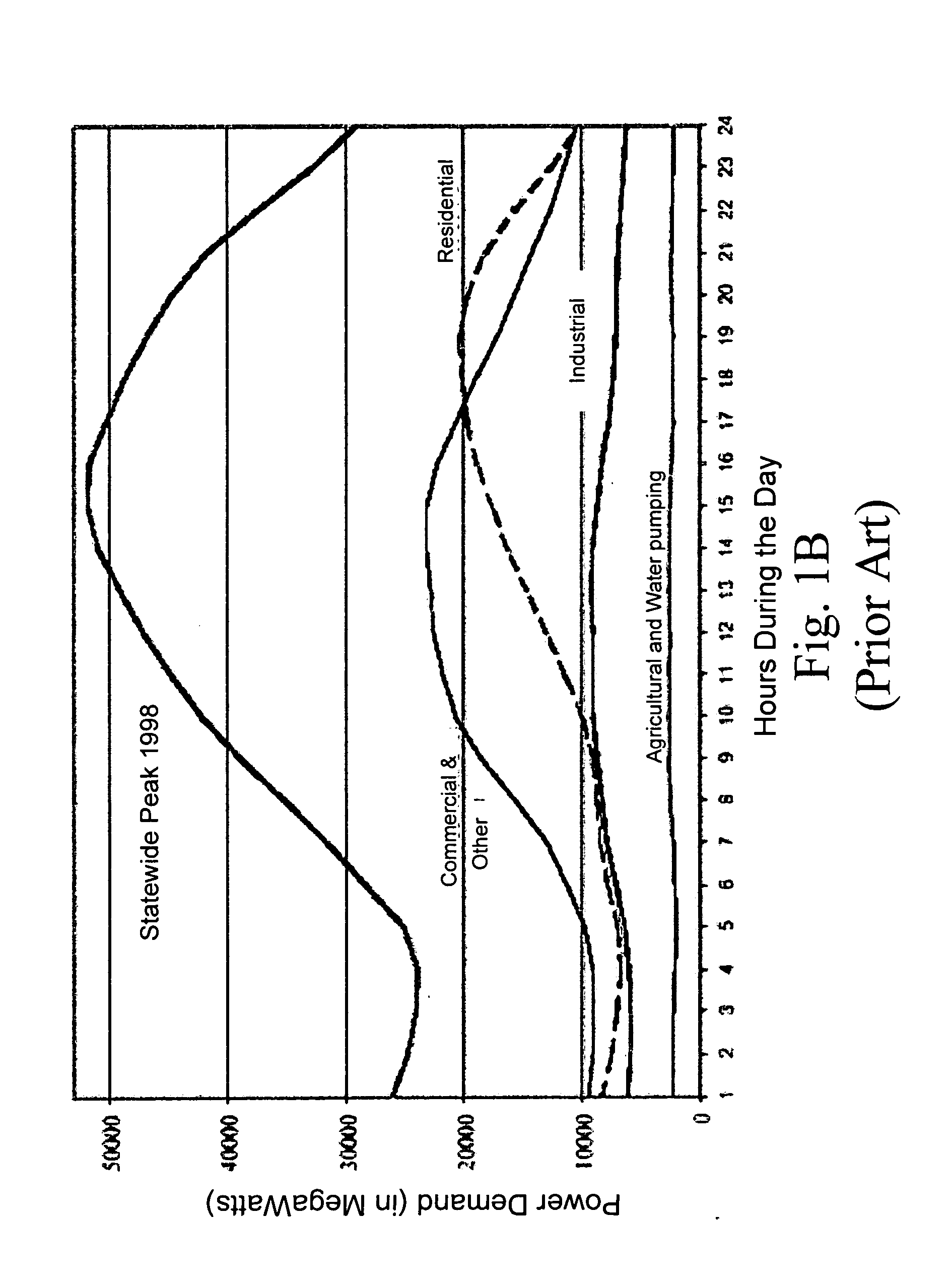
A problem confronting utility companies today is the great variance in total energy demand on a network between peak and off-peak times during the day.
The capacity of solar cells in generating electricity, however, is limited to the time period when they are exposed to solar radiation.
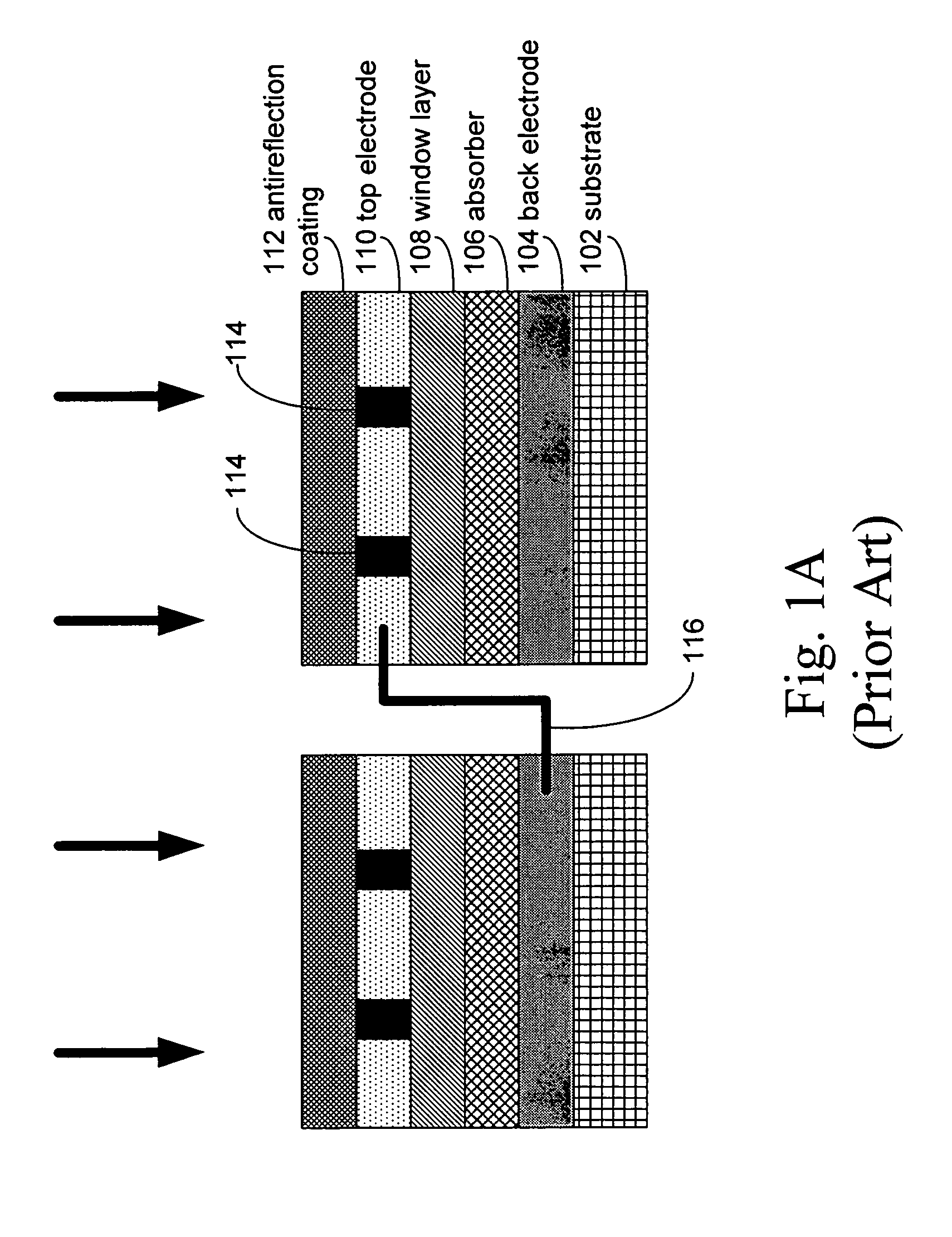
However, even when a TCO layer is present, a bus bar network 114 is typically needed in conventional solar cells to draw off current since the TCO has too much resistance to efficiently perform this function in larger solar cells.
Although such cells are highly efficient when they are smaller, larger planar solar cells have reduced efficiency because it is harder to make the semiconductor films that form the junction in such solar cells uniform.
Furthermore, the occurrence of pinholes and similar flaws increase in larger planar solar cells.
These features can cause shunts across the junction.
However, even the cylindrical solar cells found in the prior art have drawbacks that do not fully address the problems faced by utility companies and energy consumers.
First, during solar radiation collection, cylindrical solar cells heat up to high temperatures.
Second, when arranged in planar arrays, cylindrical solar cells often cast a shadow on neighboring cells, resulting in a reduction in the amount of solar cell surface area that is exposed to direct solar radiation.
Peak electricity demands in many communities, however, occurs much later in the afternoon when people return home and need to cook, heat or cool their homes and when the long exposure of building rooftops to daylight begins to heat the building up, thereby increasing the load on air conditioners.
The discrepancy between solar peak capacity and peak electricity demand hampers the utility of conventional cylindrical solar cells.
The tracking requirement associated with many conventional cylindrical solar cell systems is disadvantageous.
However, the periodical mechanical adjustments associated with such tracking devices require relatively complex, sometimes elaborate, and often costly structures.
In addition, power is required to adjust the tracking devices, thereby reducing the overall efficiency of the system.
Each of the above drawbacks has an adverse affect on cylindrical solar cell performance and / or the cost of making cylindrical solar cells.
However, the systems disclosed in these references are unsatisfactory because they are costly.

Method used


Image

  • Assemblies of cylindrical solar units with internal spacing
  • Assemblies of cylindrical solar units with internal spacing
  • Assemblies of cylindrical solar units with internal spacing

Examples


Embodiment Construction

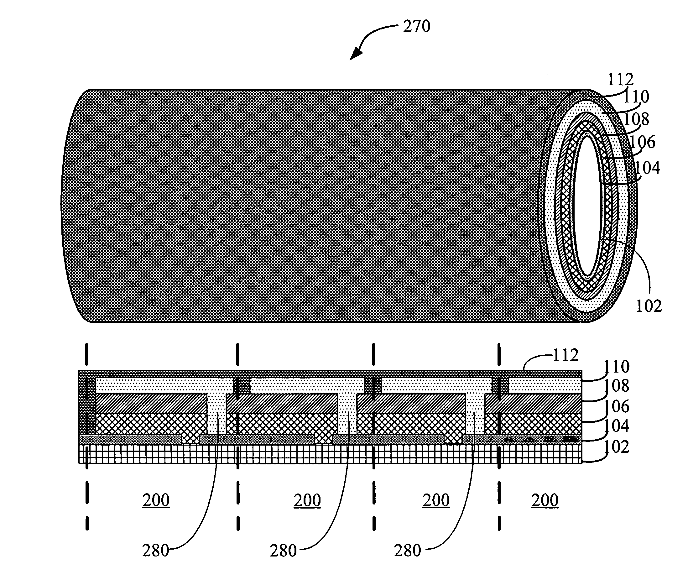
[0056] Disclosed herein are exemplary structures of elements within cylindrical solar units that form part of the novel solar cell arrangements in accordance with some embodiments of the present invention. Each cylindrical solar unit can be a solar cell as described in conjunction with FIG. 2A below or a solar module as described in conjunction with FIG. 2B, below. In some embodiments of the present invention, solar cell arrangements of the present invention comprise a single solar cell panel. In some embodiments of the present invention, solar cell arrangements of the present invention comprise a plurality of solar cell panels.

5.1 Basic Structure

[0057]FIG. 2A illustrates the cross-sectional view of an exemplary embodiment of a cylindrical solar unit that is a solar cell 200. In some embodiments, the cylindrical substrate is either (i) tubular shaped or (ii) a rigid solid. In some embodiments the cylindrical substrate is a flexible tube, a rigid tube, a rigid solid, or a flexible ...


PUM


Abstract

A solar cell arrangement comprising a solar cell assembly having cylindrical solar units arranged parallel or approximately parallel to each other in a common plane. A first and a second cylindrical solar unit in the plurality of solar cell units are separated from each other by a spacer distance thereby allowing direct sunlight to pass between the cylindrical solar units. Each cylindrical solar unit in the plurality of solar units is at least a separation distance away from an installation surface.

Description

1. FIELD OF THE INVENTION [0001] This invention relates to arrangements of solar units. More specifically, this invention relates to systems and methods for spatially arranging cylindrical solar units within a solar cell panel or solar cell array to optimize conversion of solar energy into electrical energy. Solar units are either solar cells or monolithically or non-monolithically integrated solar modules. 2. BACKGROUND OF THE INVENTION [0002] A problem confronting utility companies today is the great variance in total energy demand on a network between peak and off-peak times during the day. This is particularly the case in the electrical utility industry. The so-called peak demand periods or load shedding intervals are periods of very high demand on the power generating equipment where load shedding can be necessary to maintain proper service to the network. These occur, for example, during hot summer days occasioned by the widespread simultaneous usage of electric air conditioni...

Claims


Application Information

Patent Timeline
IPC IPC(8): H02N6/00
CPCH01L31/035281Y02E10/52H01L31/0547H01L31/0504H01L31/046
Inventor BULLER, BENYAMINGRONET, CHRIS M.TRUMAN, JAMES K.
Owner SOLYNDRA
Learn More