
Continuous inkjet printing method

a technology of inkjet printing and continuous ink, which is applied in the field of inkjet ink, can solve the problems of reducing print quality, forming additional droplet types undetected, and reducing print quality, so as to reduce dynamic surface tension, improve ink film formation on the catcher face, and restore the effect of operating print margin

Active Publication Date: 2013-03-21
EASTMAN KODAK CO
View PDF19 Cites 22 Cited by
  • Summary
  • Abstract
  • Description
  • Claims
  • Application Information

AI Technical Summary

Benefits of technology

The invention improves the properties of ink on the catcher face by reducing the dynamic surface tension of the ink during printing. This allows for better ink film formation and reduces the likelihood of printing defects such as coalescement and excessive foam formation. This results in improved printing quality and efficiency.

Problems solved by technology

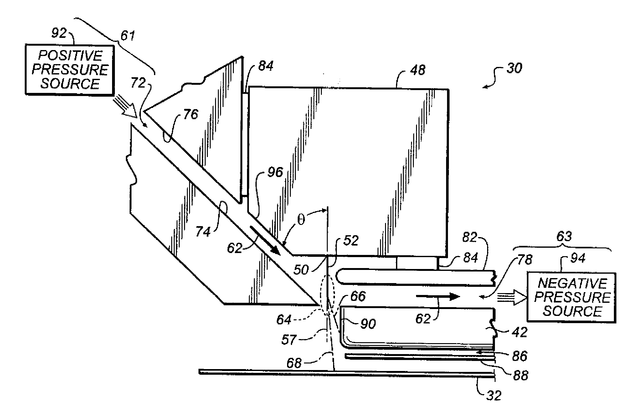
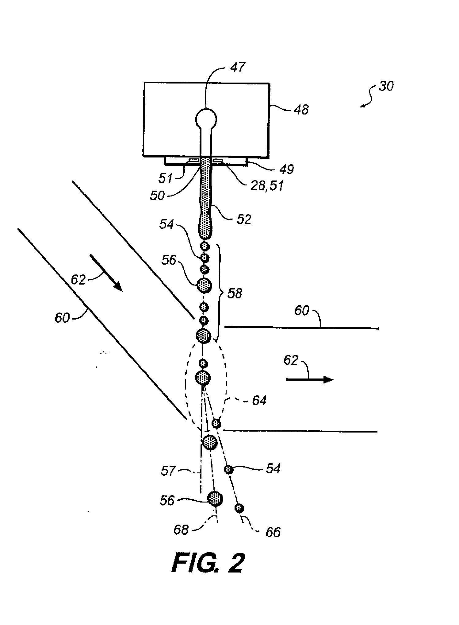
Additional droplet types undesirably can form, including satellites and coalesced small non-printing drops.
If the air flow is insufficient, such that small non-printing drops are not deflected far enough, they can reach the substrate being printed and a marking error of unintended printing occurs that is referred to as “dark defect” (DD), reducing print quality.
If the air flow is too aggressive, large printing drops may also be swept into the gutter and not mark the substrate at all, creating another marking error due to the incomplete print image that is referred to as “pick out” (PO).
The problem arises, however, that the print margin in a CIJ printing press is both sensitive to the details of the image to be printed and to the printing speed.
In particular, when airflows are set to prevent DD, the printing of images containing abrupt changes between regions of continuous white and black, as in a logo, exacerbates the PO defect under high speed printing conditions.
In addition, the stability of the DOD ink compositions to fluidic forces associated with CIJ recirculating filtration is not assured, since the inks are delivered to the nozzles by passive fluidic forces and not active mechanical pumping, and since the fired ink that is ejected from the nozzles is never re-used.

Method used


Image

  • Continuous inkjet printing method
  • Continuous inkjet printing method
  • Continuous inkjet printing method

Examples


examples

[0118]The suffix (c) designates control or comparative ink jet ink compositions, while the suffix (e) indicates example ink jet ink compositions. The abbreviation “Wt %” indicates the ingredient weight percent. Carbon black pigment dispersion content is based on the weight percent of carbon black.

Preparation of Continuous Ink Jet Ink Samples

Polymeric Dispersant and Additive Preparation

Polymeric Dispersant P-1

[0119]In a representative procedure, a 5-liter, three-necked round bottom flask equipped with a mechanical stirrer, a reflux condenser, and a gas inlet was charged with 225 g of 1-methoxy-2-propanol and was sparged with nitrogen. Akzo-Nobel Chemicals, Inc., initiator Perkadox AMBN-GR (1.9 g) was added with stirring. A reactant reservoir was charged with 225 g of 1-methoxy-2-propanol, 23.4 g of 1-dodecanethiol, 203.5 g of benzyl methacrylate, 165.0 g of stearyl methacrylate, and 181.5 g of methacrylic acid, and the solution was degassed by nitrogen sparging. AMBN-GR (7.7 g) was a...


PUM


Abstract

A method of printing an image with a continuous inkjet printer system employing a jetting module including a nozzle in fluid communication with a liquid ink source and a catcher including a liquid drop contact face; wherein the liquid ink is an aqueous inkjet black ink comprising a black colorant and at least one surfactant selected to provide a 10-ms dynamic surface tension of less than 54 mN / m. Full color images may be printed by further employing at least second, third and fourth jetting modules and yellow, magenta and cyan inks each also comprising a surfactant selected to provide a 10-ms dynamic surface tension of less than 54 mN / m for each ink. The ink compositions provide for fluid properties on the drop catcher face that minimize printing defects that can occur during drop deflection during the printing of high dynamic range images at high speed.

Description

CROSS REFERENCE TO RELATED APPLICATIONS[0001]Reference is also made to commonly assigned, co-pending U.S. Ser. No. ______ (Kodak Docket K000608) entitled “Ink Set for Continuous Inkjet Printing” and Ser. No. ______ (Kodak Docket 96735) entitled “Ink Composition for Continuous Inkjet Printing” filed concurrently herewith, the disclosures of which are incorporated herein by reference.FIELD OF THE INVENTION[0002]The invention relates generally to the field of inkjet inks, and in particular to aqueous pigmented ink compositions for continuous inkjet printing. More specifically, the invention relates to black inkjet inks and full colored inkjet ink sets with dynamic surface tension properties especially suitable for high speed continuous inkjet printing.BACKGROUND OF THE INVENTION[0003]In one form of binary continuous inkjet (CIJ) printing, such as described in U.S. Pat. Nos. 6,554,410; 6,588,888; 6,863,385; and 6,866,370, a printhead produces fluid drops by thermal stimulation of the fl...

Claims


Application Information

Patent Timeline
Patent Type & Authority Applications(United States)
IPC IPC(8): B41J2/105
CPCB41J2/105C09D11/40C09D11/38C09D11/324
Inventor NELSON, DAVID JOHNLINDSTROM, BRIAN L.BERMEL, ALEXANDRA DILAUROSOWINSKI, ALLAN FRANCISJEANMAIRE, DAVID LOUISGRIFFIN, TODD RUSSELL
Owner EASTMAN KODAK CO
Learn More