
Camera module

Active Publication Date: 2013-03-21
LG INNOTEK CO LTD
View PDF2 Cites 32 Cited by
  • Summary
  • Abstract
  • Description
  • Claims
  • Application Information

AI Technical Summary

Benefits of technology

The camera module in this patent has a function to automatically focus on the subject, which improves image quality. It also integrates the barrel and bobbin to reduce assembly tolerance issues, which saves money and reduces the likelihood of defects during production.

Problems solved by technology

However, the thus-configured camera module is disadvantageous in that an optical tilt and shift may be generated by unevenness of adhesive coated for assembling multiple components and assembly tolerance in components to decrease the quality of images due to accumulated errors.
Another disadvantage is that separate focus adjustment process is inevitably needed after assembly of each component due to the assembly tolerance in components.

Method used


Image

  • Camera module
  • Camera module
  • Camera module

Examples


Embodiment Construction

[0016]The following description is not intended to limit the invention to the form disclosed herein. Consequently, variations and modifications commensurate with the following teachings, and skill and knowledge of the relevant art are within the scope of the present invention. The embodiments described herein are further intended to explain modes known of practicing the invention and to enable others skilled in the art to utilize the invention in such, or other embodiments and with various modifications required by the particular application(s) or use(s) of the present invention.

[0017]The disclosed embodiments and advantages thereof are best understood by referring to FIGS. 1-5 of the drawings, like numerals being used for like and corresponding parts of the various drawings. Other features and advantages of the disclosed embodiments will be or will become apparent to one of ordinary skill in the art upon examination of the following figures and detailed description. It is intended ...


PUM


Abstract

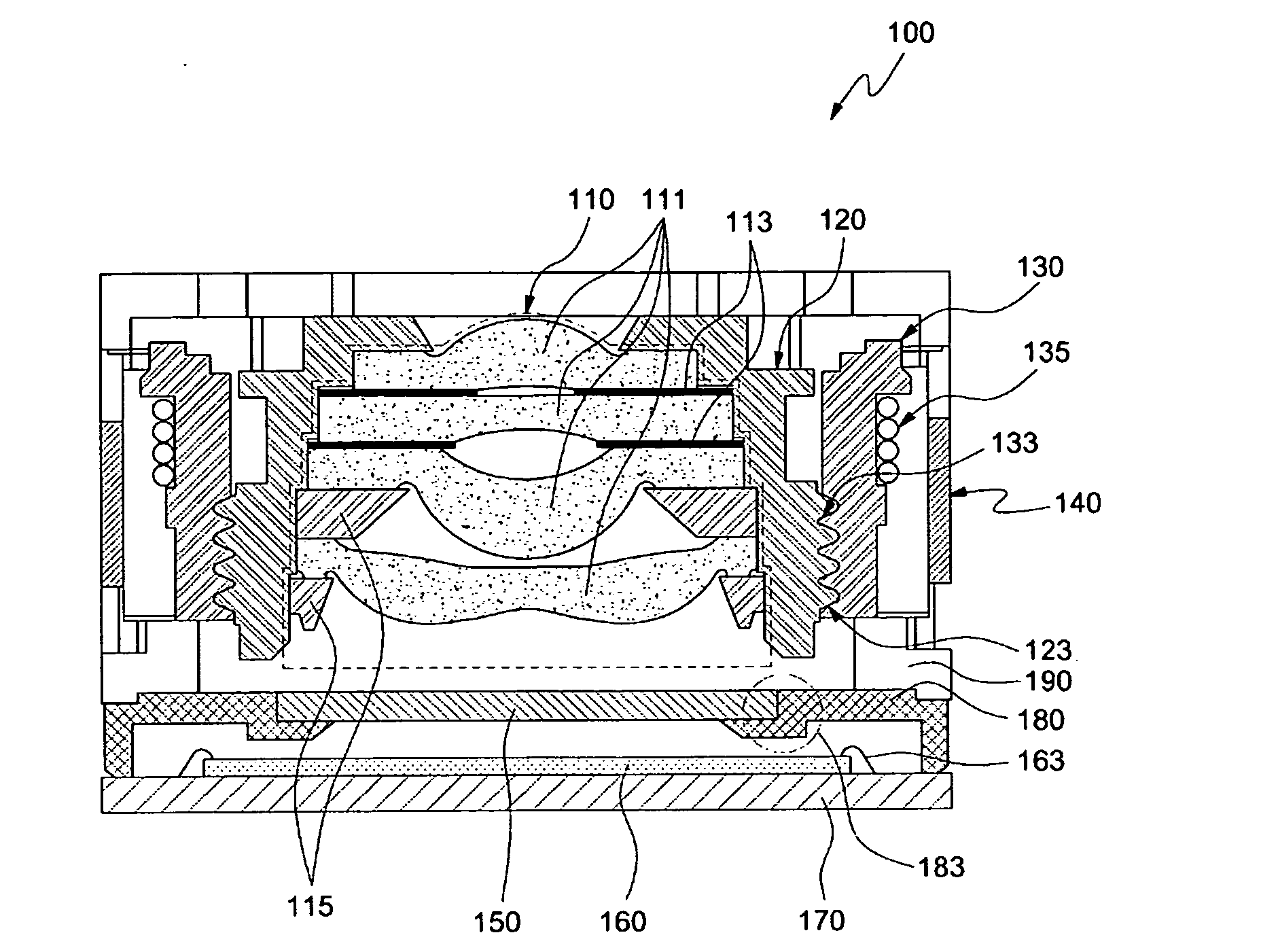
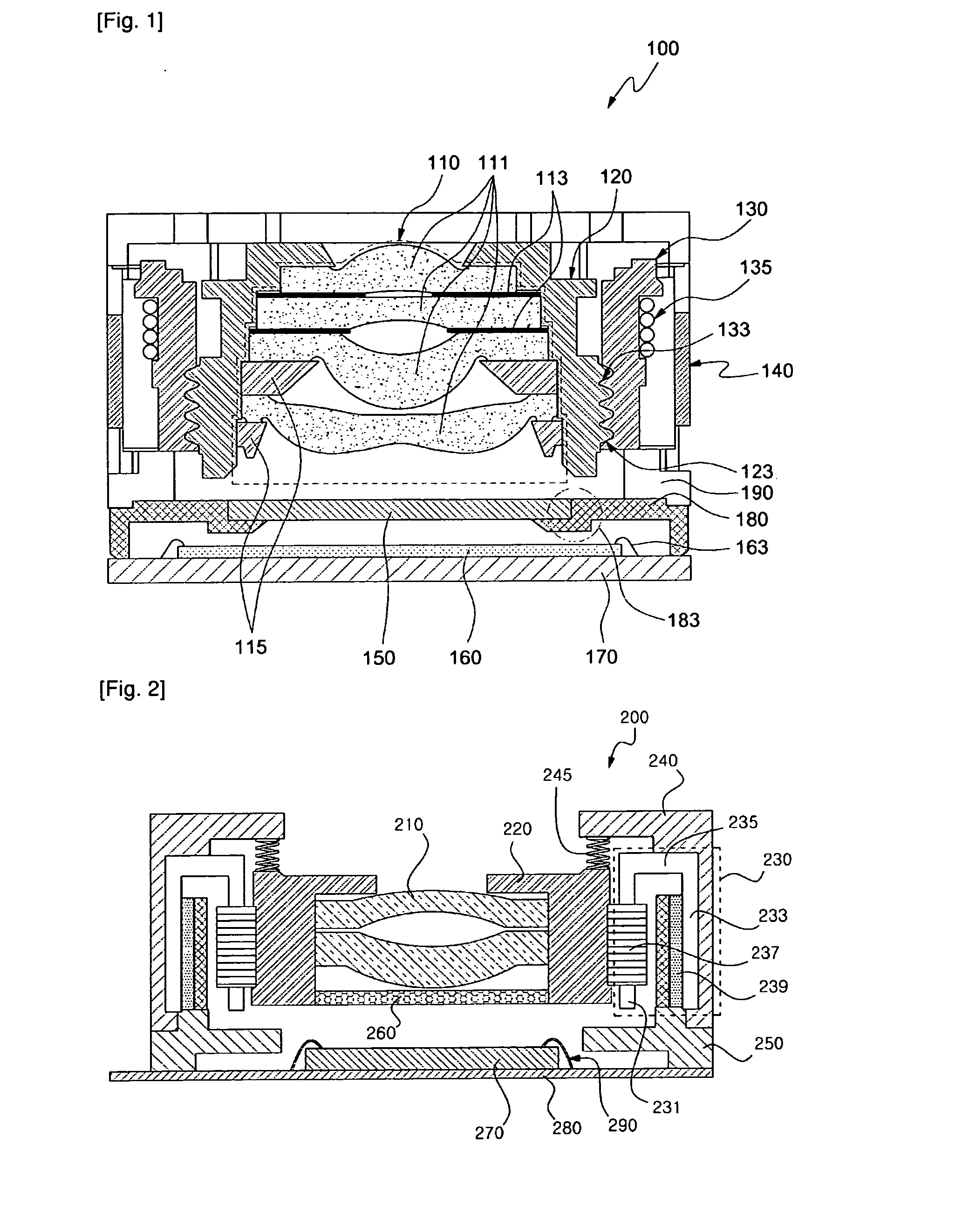
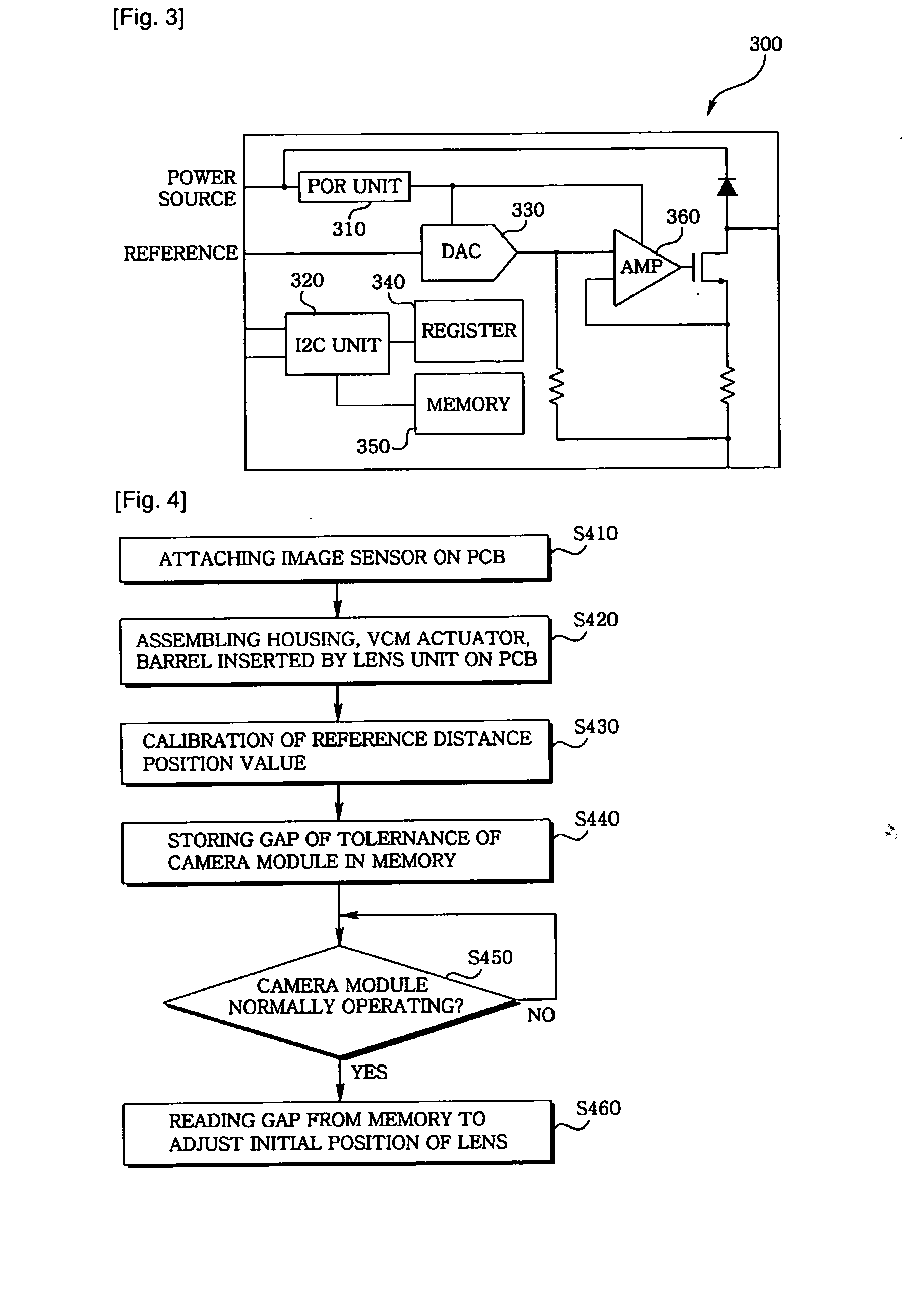
The present invention relates to a camera module having an auto focus function, the module including a lens unit having at least one lens, a barrel into which the lens unit is inserted, and connected by a VCM (Voice Coil Motor) actuator, and an image sensor discretely positioned from the lens unit to convert light having passed the lens unit to an electrical signal, where the VCM actuator includes a gap of a reference distance position value which is a position of an object catering to a lens focal length according to the camera module, and information on a focus-met lens position value, and adjusts an initial position of the lens by using the gap of reference distance position value of the lens position value during operation of the camera module.

Description

TECHNICAL FIELD[0001]The present invention relates to a camera module camera module having an auto-focus function.BACKGROUND ART[0002]Digital camera modules are currently being incorporated into a variety of host devices. Such host devices include cellular telephones, personal data assistants (PDAs), computers, and so forth. Consumer demand for digital camera modules in host devices continues to grow.[0003]The camera modules having auto focus adjusting function is configured such that a barrel protecting a conventional lens unit is coupled to a bobbin wounded by a coil via a screw, where the bobbin is interposed between a holder adhesively contacted at a floor surface thereof to a printed circuit board and a motor base.[0004]However, the thus-configured camera module is disadvantageous in that an optical tilt and shift may be generated by unevenness of adhesive coated for assembling multiple components and assembly tolerance in components to decrease the quality of images due to acc...

Claims


Application Information

Patent Timeline
IPC IPC(8): H04N5/232
CPCG02B7/08G02B13/001G02B13/004H04N5/232H04N5/2254H04N5/2257H02K41/0356H04N23/57H04N23/55G03B13/36G03B30/00H04N23/69
Inventor KIM, CHANGHYUN
Owner LG INNOTEK CO LTD
Learn More