Ceramic firing furnace

Inactive Publication Date: 2012-02-16
SAMSUNG ELECTRO MECHANICS CO LTD
View PDF2 Cites 13 Cited by
  • Summary
  • Abstract
  • Description
  • Claims
  • Application Information

AI Technical Summary

Benefits of technology

[0010]An aspect of the present invention provides a ceramic firing furnace in which a uniform gas atmos

Problems solved by technology

However, the conventional firing furnace has difficulty in smoothly supplying a gas to the interior of the calcinations furnace.
Namely, in the related art, it is not easy to uniformly form a gas atmosphere within the calcinations furnace, and this pro

Method used


Image

  • Ceramic firing furnace
  • Ceramic firing furnace
  • Ceramic firing furnace

Examples


Embodiment Construction

[0039]Before the detailed description, it should be noted that the terms used in the present specification and the claims are not to be limited to their lexical meanings, but are to be interpreted to conform with the technical idea of the present invention under the principle that the inventor can properly define the terms for the best description of the invention made by the inventor. Therefore, the embodiments and the constitution illustrated in the attached drawings are merely preferable embodiments according to the present invention, and thus they do not express all of the technical idea of the present invention, so that it should be understood that various equivalents and modifications can exist which can replace the embodiments described in the time of the application.

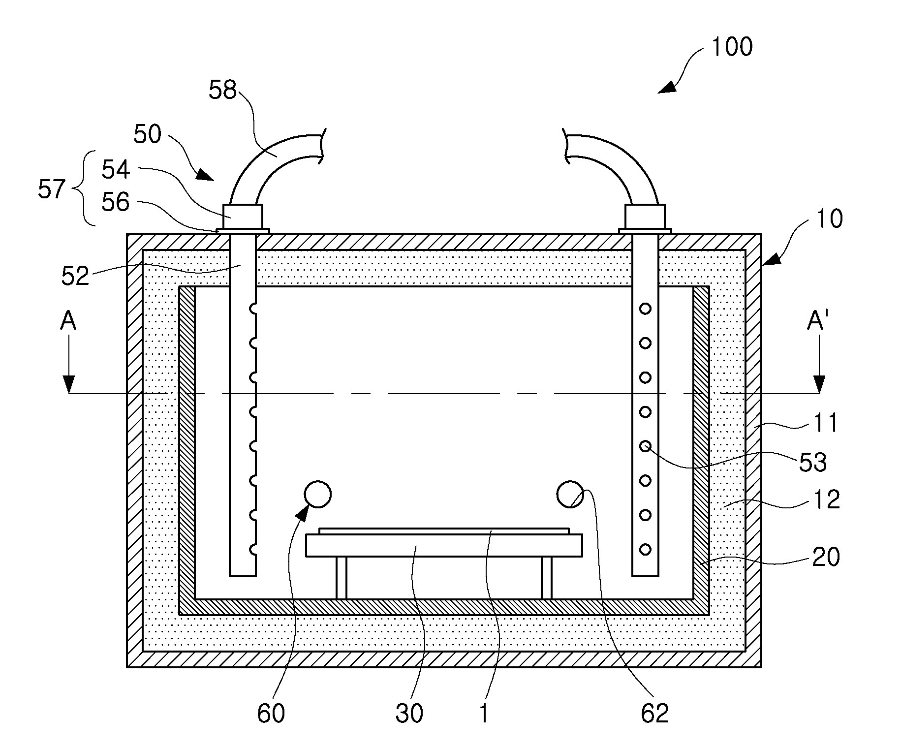
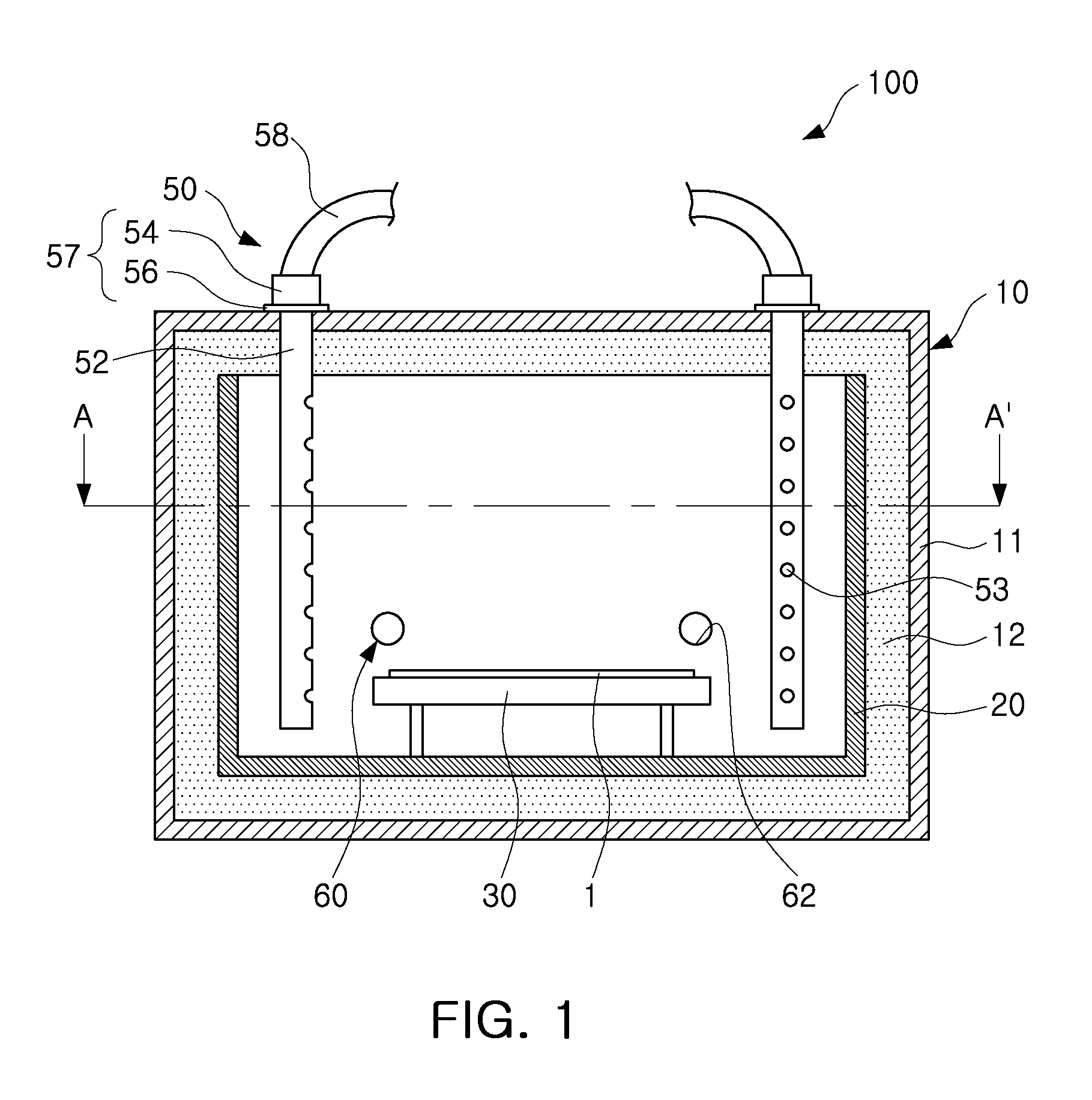
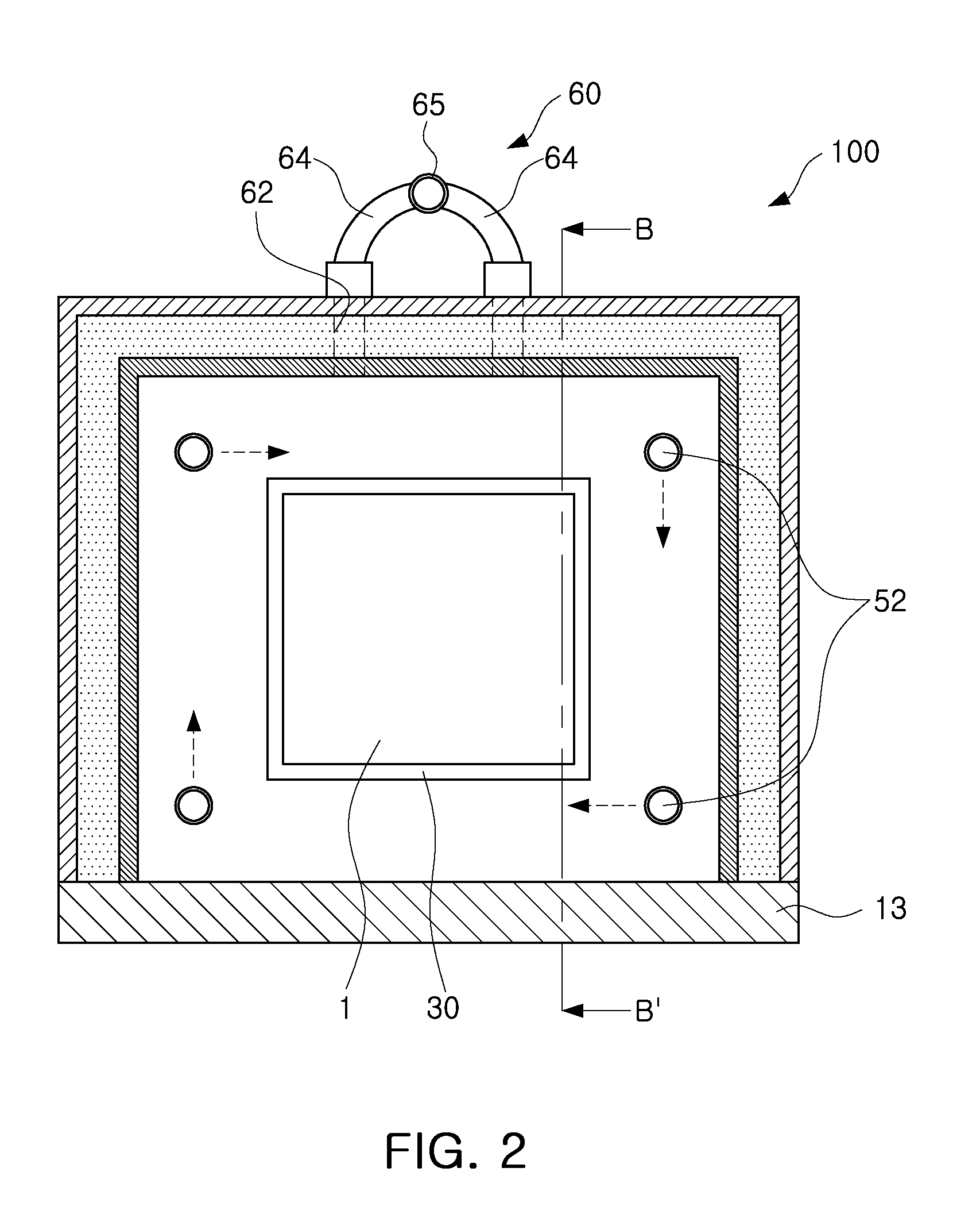
[0040]Exemplary embodiments of the present invention will now be described in detail with reference to the accompanying drawings. The invention may, however, be embodied in many different forms and should not be ...


PUM


Abstract

A ceramic firing furnace is provided. A uniform gas atmosphere is formed in the ceramic firing furnace to thus minimize a defective ceramic substrate when the ceramic substrate is fired. The ceramic firing furnace includes: a case having an internal space in which a shaped body is disposed; a heating element disposed in the interior of the case and radiating heat; and a plurality of air supply units fastened through the case such that the plurality of air supply units are rotatable by an external force, and supplying a gas to the internal space of the case.

Description

CROSS-REFERENCE TO RELATED APPLICATIONS[0001]This application claims the priority of Korean Patent Application No. 10-2010-0076845 filed on Aug. 10, 2010, in the Korean Intellectual Property Office, the disclosure of which is incorporated herein by reference.BACKGROUND OF THE INVENTION[0002]1. Field of the Invention[0003]The present invention relates to a firing furnace and, more particularly, to a ceramic firing furnace capable of smoothly supplying gas to the interior of a firing furnace and discharging it.[0004]2. Description of the Related Art[0005]In general, a ceramic electronic device using a ceramic may include a multilayer ceramic capacitor (MLCC), a varister, a ferrite, a piezo-electric body, and the like.[0006]The multilayer ceramic shaped body, a basis of such a ceramic electronic device, is completed through a process of manufacturing a shaped body by shaping a ceramic raw material into a certain shape and firing the shaped body in a firing furnace.[0007]In performing t...

Claims


Application Information

Patent Timeline
IPC IPC(8): F27B14/06
CPCF27B5/06F27B17/0041F27B17/0075F27B5/16F27B2005/165
Inventor YOO, WON HEECHANG, BYEUNG GYUPARK, YUN HWI
Owner SAMSUNG ELECTRO MECHANICS CO LTD
Why Eureka
Try Eureka