High-pressure cleaning appliance

a cleaning appliance and high-pressure technology, applied in the direction of cleaning processes and utensils, cleaning using liquids, chemistry apparatus and processes, etc., can solve the problems of requiring considerable time for the removal of the heat exchanger in order to gain access to the at least one second functional device, and achieves convenient disconnection, easy maintenance of the high-pressure cleaning appliance, and easy spaced relation.

Inactive Publication Date: 2013-03-28
ALFRED KARCHER GMBH & CO KG
View PDF5 Cites 0 Cited by
  • Summary
  • Abstract
  • Description
  • Claims
  • Application Information

AI Technical Summary

Benefits of technology

[0029]Preferably, the functional devices and/or functional device receptacles for functional devices required for operation of the high-pressure cleaning appliance are all comprised by the first appliance unit and/or the second appliance unit. This allows the construction of the high-pressure cleaning appliance to be particularly compact, the functional devices or functional device receptacles all being part of the first appliance unit or the second appliance unit.
[0030]Preferably, the high-pressure cleaning appliance comprises a pump set for increasing the liquid pressure, said pump set being connected to the heat exchanger via a liquid discharge conduit, wherein the liquid discharge conduit can be releasably connect...

Problems solved by technology

Experience shows that in particular the removal of the heat exchanger in order t...

Method used


Image

  • High-pressure cleaning appliance
  • High-pressure cleaning appliance
  • High-pressure cleaning appliance

Examples


Embodiment Construction

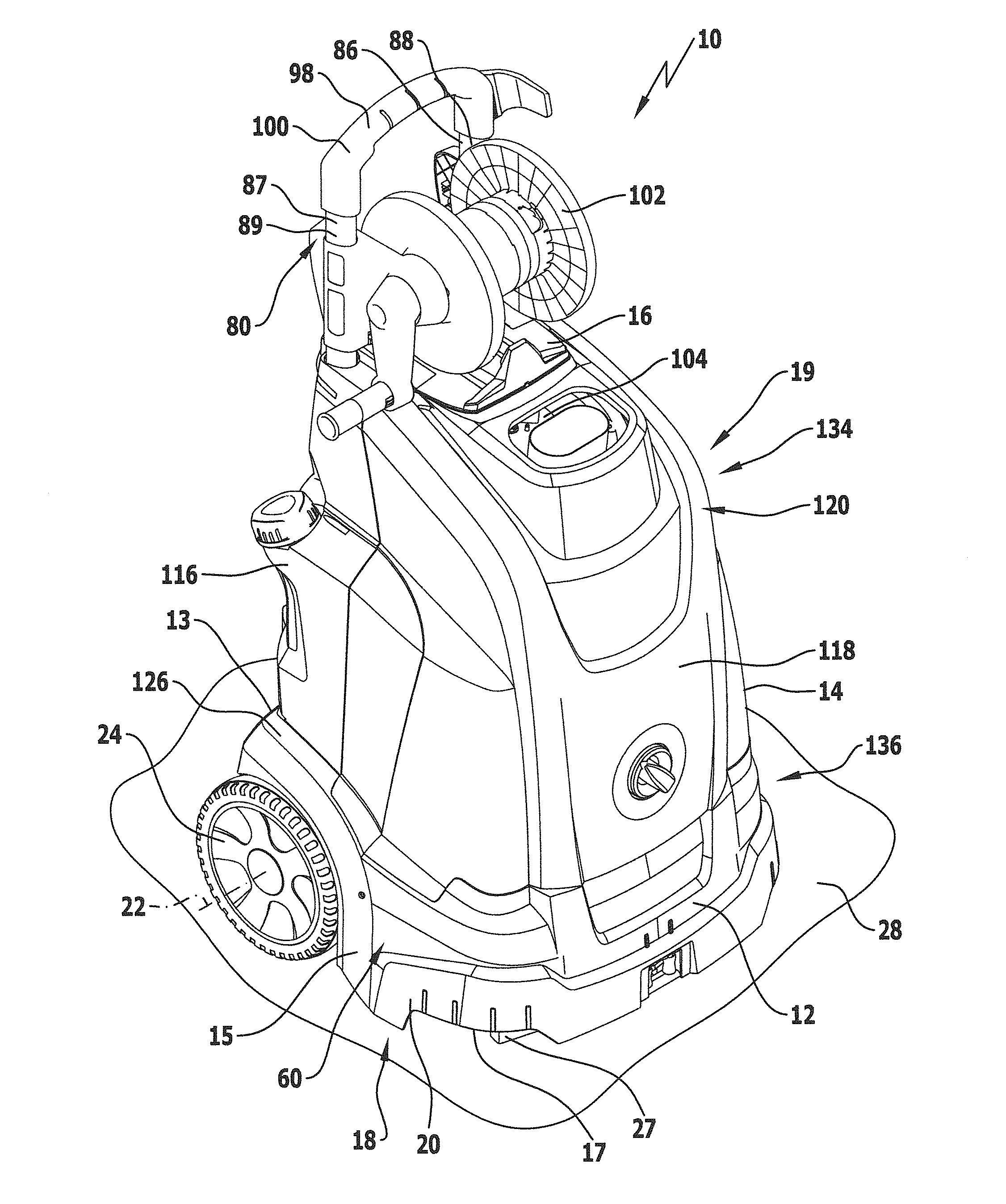
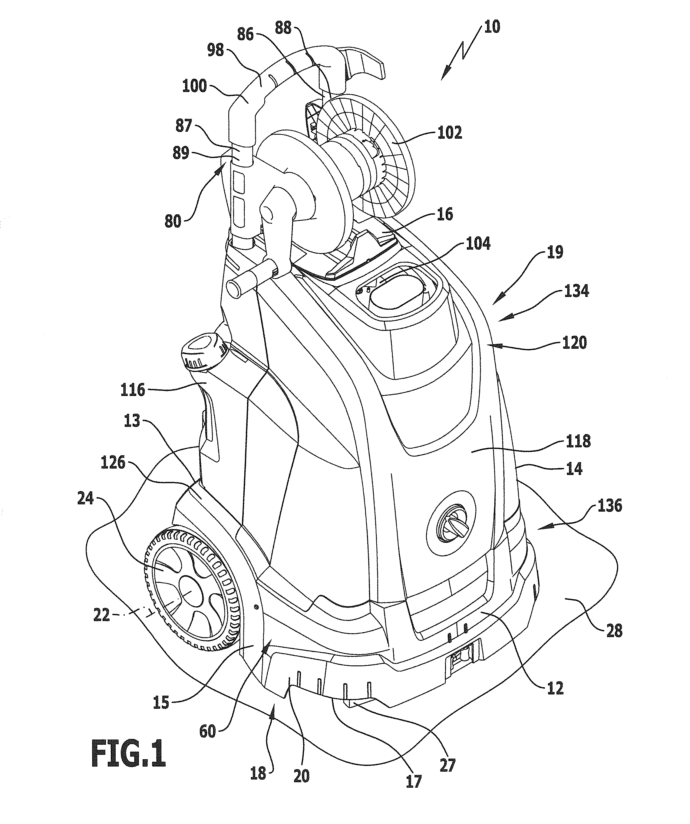
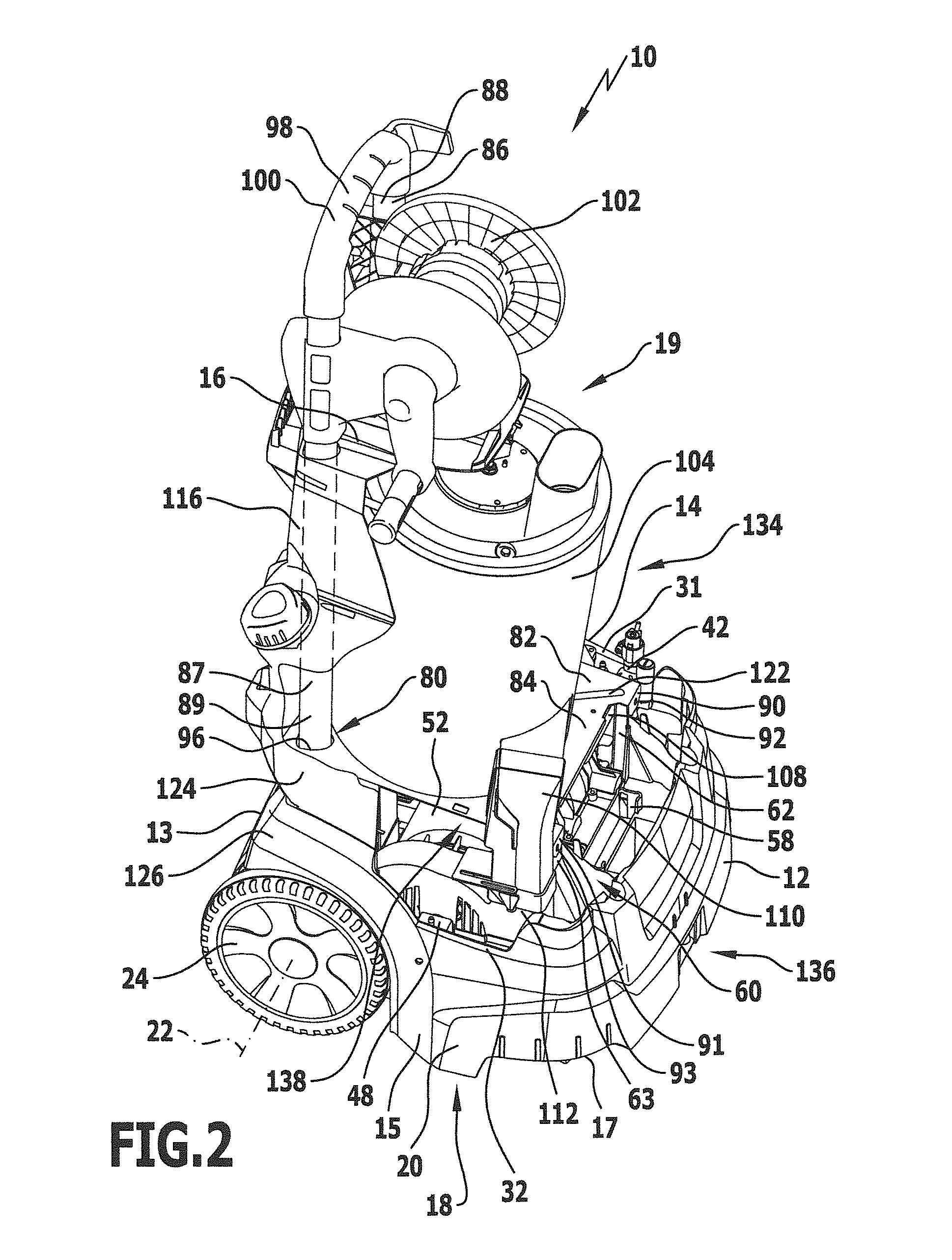
[0042]A preferred embodiment of a high-pressure cleaning appliance in accordance with the invention is fully or partially shown in the perspective views of FIGS. 1 to 4 and generally designated therein by the reference numeral 10. The high-pressure cleaning appliance 10 has a front side 12, a back side 13, a left side 14, a right side 15, a top side 16 and a bottom side 17.

[0043]The high-pressure cleaning appliance 10 comprises a lower part 18, partially shown in FIGS. 6 and 7, and an upper part 19 mounted on the lower part 18, the construction of the upper part 19 being described in more detail below. The lower part 18 has a one-piece chassis 20 which is made of a plastics material and holds two wheels 23 and 24 rotatable about a common rotation axis 22 in the areas of transition from the left side 14 to the back side 13 and from the right side 15 to the back side 13.

[0044]On the bottom side 17 near the front side 12, the chassis 20 forms two support elements in the form of support...


PUM


Abstract

The invention relates to a high-pressure cleaning appliance comprising a first functional device required for operation in the form of a heatable heat exchanger for heating a liquid that is dischargeable from the high pressure cleaning appliance, and at least one further, second functional device required for operation which is arranged below the heat exchanger. In order to develop such a high-pressure cleaning appliance such that it is more user friendly to maintain, the invention proposes that the high-pressure cleaning appliance comprise a first appliance unit having a carrying device on which the heat exchanger is held, and a second appliance unit having a support device on which the at least one second functional device is held, and that the carrying device be releasably connectable to the support device in a force-locked and/or positively-locked manner.

Description

[0001]This application is a continuation of international application number PCT / EP2009 / 063437 filed on Oct. 14, 2009.[0002]The present disclosure relates to the subject matter disclosed in international application number PCT / EP2009 / 063437 of Oct. 14, 2009, which is incorporated herein by reference in its entirety and for all purposes.BACKGROUND OF THE INVENTION[0003]The invention relates to a high-pressure cleaning appliance comprising a first functional device required for operation in the form of a heatable heat exchanger for heating a liquid that can be discharged from the high pressure cleaning appliance, and at least one further, second functional device required for operation which is arranged below the heat exchanger.[0004]High-pressure cleaning appliances of the generic kind are known in which labour-intensive disassembly of the high-pressure cleaning appliance is required to perform maintenance on the at least one second functional device which is arranged inaccessibly be...

Claims


Application Information

Patent Timeline
IPC IPC(8): B08B3/10B08B3/02
CPCB08B3/026B08B2203/007B08B3/10B08B3/02B08B2203/0211
Inventor SCHWAB, WERNERGOETZ, JOHANNES
Owner ALFRED KARCHER GMBH & CO KG
Why Eureka
Try Eureka