
Borehole tool heat transfer altering system and method, and method of heating borehole fluid

Inactive Publication Date: 2013-03-28
BAKER HUGHES INC
View PDF4 Cites 0 Cited by
  • Summary
  • Abstract
  • Description
  • Claims
  • Application Information

AI Technical Summary

Benefits of technology

The patent text describes a method of heating and pumping borehole fluids using a thermoelectric material. The method increases efficiency by improving heat transfer and reducing viscosity of the fluid, resulting in easier pumping.

Problems solved by technology

Operating devices at temperatures outside of recommended temperature ranges can detrimentally affect performance of the device including efficiency and durability, for example.

Method used


Image

  • Borehole tool heat transfer altering system and method, and method of heating borehole fluid
  • Borehole tool heat transfer altering system and method, and method of heating borehole fluid
  • Borehole tool heat transfer altering system and method, and method of heating borehole fluid

Examples


Embodiment Construction

[0014]A detailed description of one or more embodiments of the disclosed apparatus and method are presented herein by way of exemplification and not limitation with reference to the Figures.

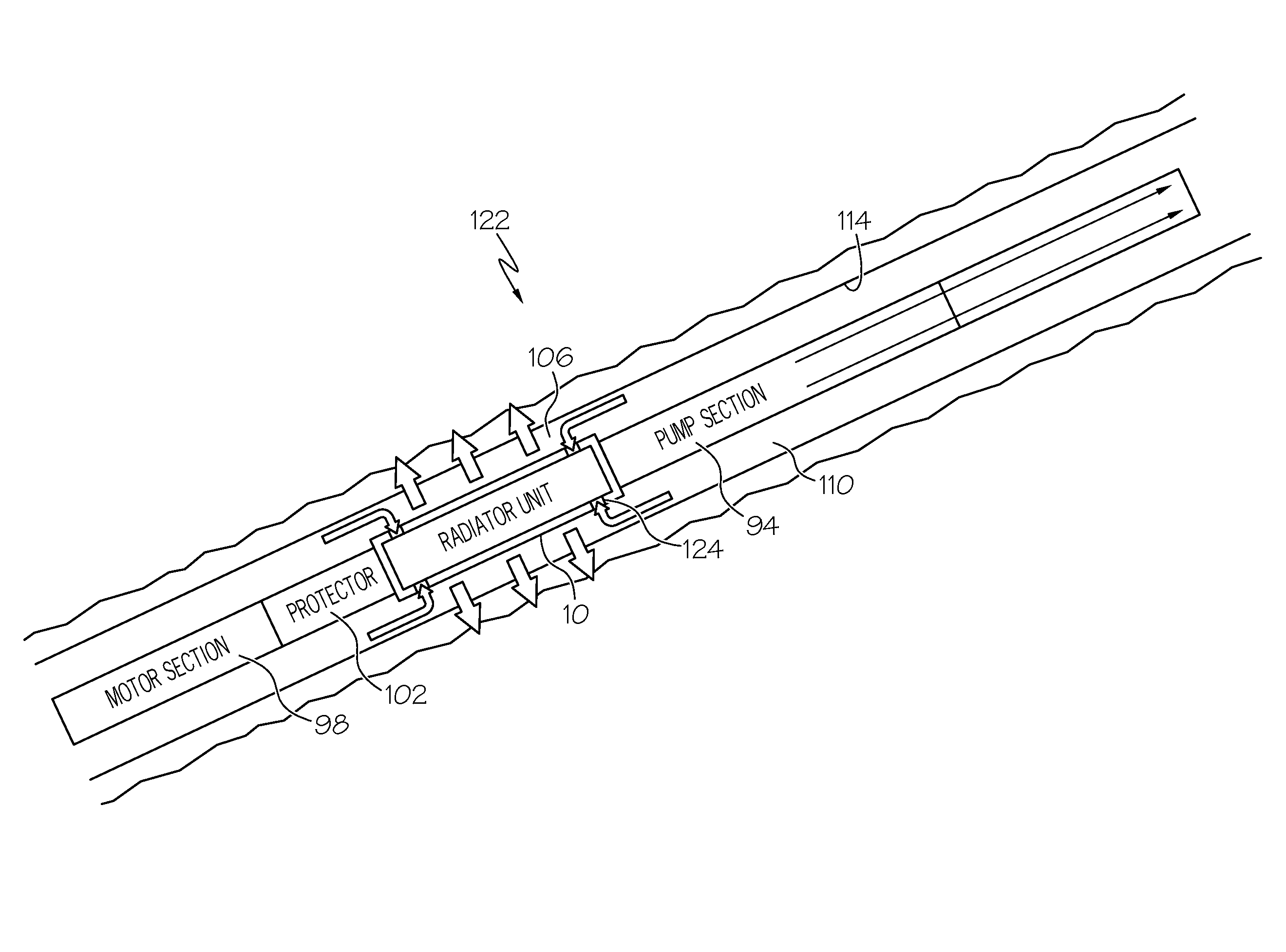
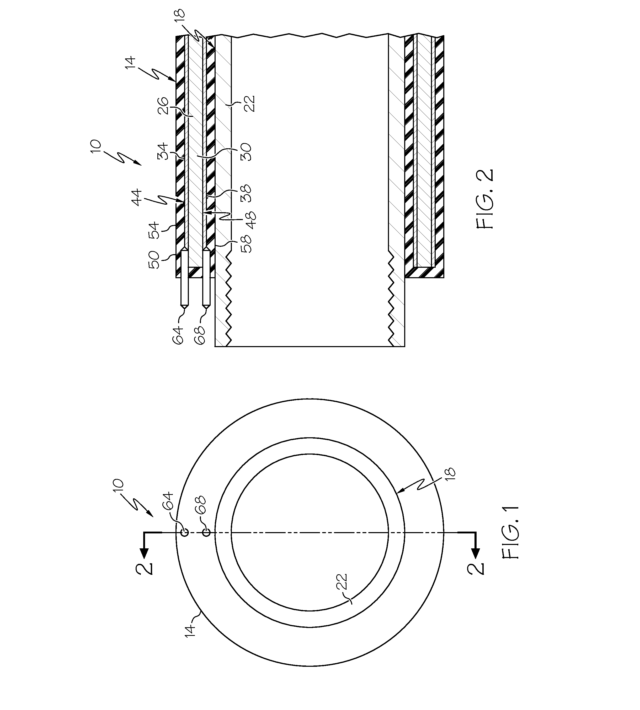
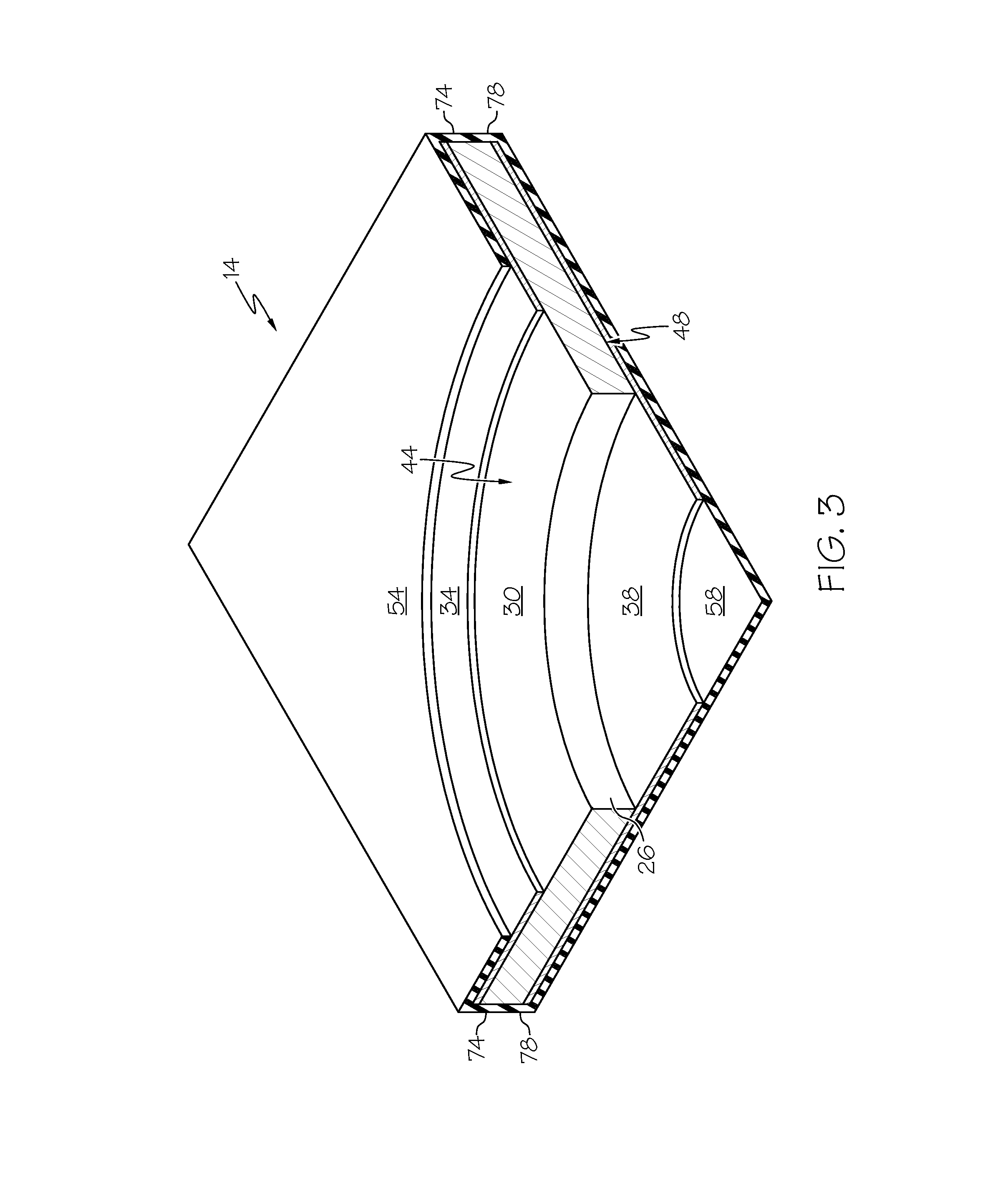
[0015]Referring to FIGS. 1-3, an embodiment of a borehole tool heat transfer altering system is disclosed generally at 10. The borehole tool heat transfer altering system 10 works on the principle of the Seebeck effect to convert electricity supplied to a thermoelectric material directly into temperature differences across the thermoelectric material, and uses no moving parts in the process. The borehole tool heat transfer altering system 10 includes, a layered assembly 14, conformed to a surface 18 (an outer surface in this embodiment) of a tubular 22. The layered assembly 14 has a core 26 of thermoelectric material 30, with conductors 34, 38, shown herein as layers of conductive material, electrically bonded to opposing surfaces 44, 48 of the thermoelectric material 30. A protector 50 including...


PUM


Abstract

A borehole tool heat transfer altering system includes, a borehole tool, and a thermoelectric material in operable communication with the borehole tool configured to alter heat transfer between the borehole tool and an environment surrounding the borehole tool.

Description

BACKGROUND[0001]Tubular systems employed in earth formation borehole applications such as the downhole completion and carbon dioxide sequestration industries, for example, often employ mechanical devices such as, motors and pumps, as well as electrical components, such as, circuits and computers for a variety of purposes. Operating temperatures of such devices can be determined by temperatures of environments surrounding the devices and by energy consumed by the devices themselves in the process of normal operation. Operating devices at temperatures outside of recommended temperature ranges can detrimentally affect performance of the device including efficiency and durability, for example. Systems and methods that aid in altering temperature of such devices are well received in the art.BRIEF DESCRIPTION[0002]Disclosed herein is a borehole tool heat transfer altering system. The system includes, a borehole tool, and a thermoelectric material in operable communication with the borehol...

Claims


Application Information

Patent Timeline
IPC IPC(8): E21B43/24
CPCE21B36/005
Inventor GERRARD, DAVID PETER
Owner BAKER HUGHES INC
Learn More