Infrared radiation detectors using carbon nanotubes-silicon vanadium oxide and or amorphous silicon nanoparticles-CNT nanocomposites and methods of constructing the same

Active Publication Date: 2017-06-13
MAGNOLIA OPTICAL TECH
View PDF6 Cites 11 Cited by
  • Summary
  • Abstract
  • Description
  • Claims
  • Application Information

AI Technical Summary

Benefits of technology

[0064]Infrared (IR) radiation detecting and sensing systems using V2O3/Amorphous silicon-carbon nanotubes nanocomposites and methods to making the same. In certain embodiments of the invention, it includes, a thermally isolated microbridge structure, random, aligned or bundled carbon nanotubes applied, first and second conducting interconnects each in electrical communication with the nanotubes. The entire microbridge structure is fabricated on a CMOS wafer with a readout design. Percolation among aligned, partially or nonaligned CNT-Silicon nanocomposites can be optimized for the IR detector application by modulating the densities of CNTs and amorphous silicon or vanadium oxide nanoparticles concentration in the thin film. The device is a microbolometer type where the ability to resolve smaller changes in temperature is highly desirable resulting in higher sensitivity IRFPAs. Three different methods for constructing the detector proposed in this application include a combination of thin films where the interface between an existing V2O3 or amorphous thin film on a suspended MEMS structure a V2O3 or silicon nanoparticle serves as the interface between the existing film and the aligned, partially aligned or random carbon nanotubes The second type is a CNT-amorphous Silicon or vanadium oxide nanocompo

Problems solved by technology

HgCdTe IR detector technology, which is cooled to 77 K for optimal operation used mecha

Method used


Image

  • Infrared radiation detectors using carbon nanotubes-silicon vanadium oxide and or amorphous silicon nanoparticles-CNT nanocomposites and methods of constructing the same
  • Infrared radiation detectors using carbon nanotubes-silicon vanadium oxide and or amorphous silicon nanoparticles-CNT nanocomposites and methods of constructing the same
  • Infrared radiation detectors using carbon nanotubes-silicon vanadium oxide and or amorphous silicon nanoparticles-CNT nanocomposites and methods of constructing the same

Examples


Example

[0076]The present disclosure relates to microbolometer structures having top layers of amorphous silicon or vanadium oxide. In some examples, combinations of carbon nanotubes, nanoparticles, and / or thin films can be deposited atop the existing top layer of amorphous silicon or top layer of vanadium oxide of a microbolometer structure. Such configurations can increase the sensitivity of the microbolometers to less than 4 mK, less than 2 mK, and in some examples less than 1 mK.

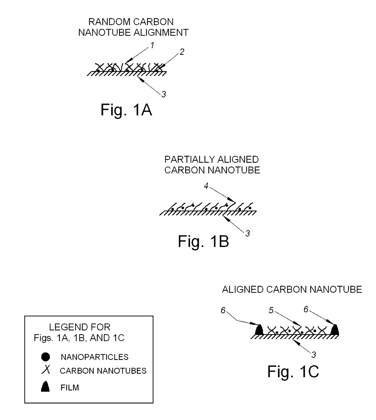
[0077]FIG. 1A depicts a top layer of a microbolometer detector structure according to one or more aspects of the disclosure. As shown in FIG. 1A, the top layer of the microbolometer detector can include a layer 3 and a layer of unaligned (e.g., randomly aligned) carbon nanotubes 1 deposited upon a surface of the layer 3. The layer 3 can be any type of substrate suitable for use in a microbolometer, and in this example can be amorphous silicon (also referred to as α-silicon) or vanadium oxide, e.g., VxOy.

[0078]Th...


PUM


Abstract

The present disclosure relates to microbolometer structures having top layers of amorphous silicon or vanadium oxide. In some examples, combinations of carbon nanotubes, nanoparticles, and/or thin films can be deposited atop the existing top layer of amorphous silicon or top layer of vanadium oxide of a microbolometer structure. Such configurations can increase the sensitivity of the microbolometers to less than 4 mK, less than 2 mK, and in some examples less than 1 mK.

Description

RELATED APPLICATIONS[0001]This application claims the benefit of U.S. Provisional Application Ser. No. 62 / 095,744, filed Dec. 22, 2014, entitled INFRARED RADIATION DETECTORS USING CARBON NANOTUBES-SILICON VANADIUM OXIDE AND OR AMORPHOUS SILICON NANOPARTICLES-CNT NANOCOMPOSITES AND METHODS OF CONSTRUCTING THE SAME, the entire disclosure of which is herein incorporated by reference.FIELD OF THE INVENTION[0002]The present invention relates generally to carbon nanotube nanocomposites and amorphous silicon or vanadium oxide nanoparticles.BACKGROUND OF THE INVENTION[0003]Photodetectors are an integral part of optical circuits and components (for example emitters, modulators, repeaters, waveguides or fibers, reflectors, resonators, detectors, IR Focal plane arrays, etc.) and are used for the sensing of electromagnetic radiation. There are several approaches to these devices. Photoconducting materials, typically semiconductors, have electrical properties that vary when exposed to electromag...

Claims


Application Information

Patent Timeline
IPC IPC(8): G01J5/02G01J5/24H01L31/09H01L31/028G01J5/08
CPCG01J5/24H01L31/095H01L31/028G01J5/0809G01J5/0853
Inventor EGERTON, ELWOOD J.SOOD, ASHOK K.
Owner MAGNOLIA OPTICAL TECH
Why Eureka
Try Eureka