Dental implant procedure by scanning a closed tray impression

Inactive Publication Date: 2018-07-12
OPHIR OPTRONICS SOLUTIONS
View PDF4 Cites 2 Cited by
  • Summary
  • Abstract
  • Description
  • Claims
  • Application Information

AI Technical Summary

Benefits of technology

[0007]The present disclosure describes new exemplary systems and methods for a closed tray solution to the problem of providing accurate scanned information for the production of dental superstructures. The advantage of the closed tray technique is that once the initial impression has been mad

Problems solved by technology

However, because of the high level of fit accuracy required, failure to achieve accurate passive fitness will incur stress on implants which can finally lead to fracture of the implant components and failure of the treatment.
The forces created in the implant due to inaccuracies in the superstructure is even able to degrade the bone surrounding the implant and may cause ischemia within the peri-implant tissue, and prevention of subsequent healing.
Non-mineral tissue may be formed around the implant, possibly resulting in mechanical damage to the bone, loosening of the implant components and fracture of the restoration.
A degree of inaccuracy is present in the transfer of the implant positions by any impression methods.
The number of transfer steps here incr

Method used


Image

  • Dental implant procedure by scanning a closed tray impression
  • Dental implant procedure by scanning a closed tray impression
  • Dental implant procedure by scanning a closed tray impression

Examples


Example

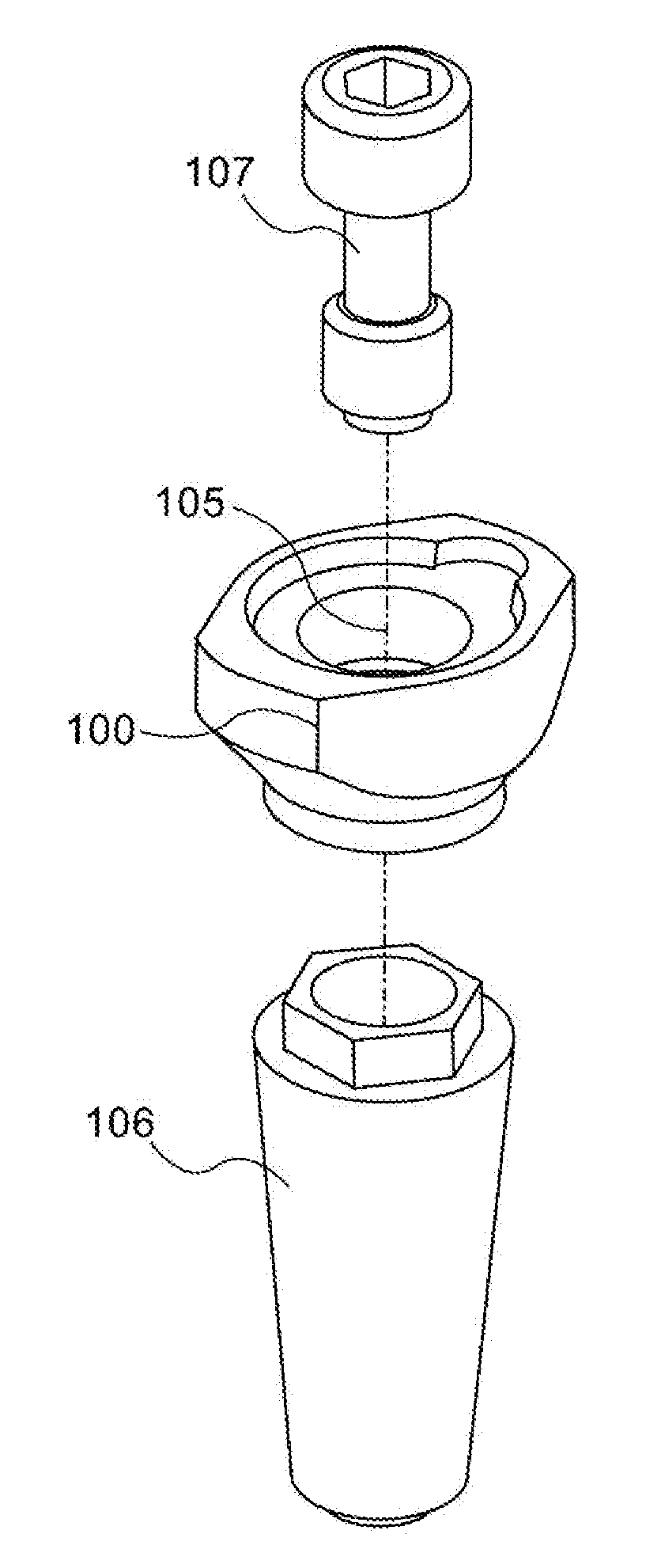
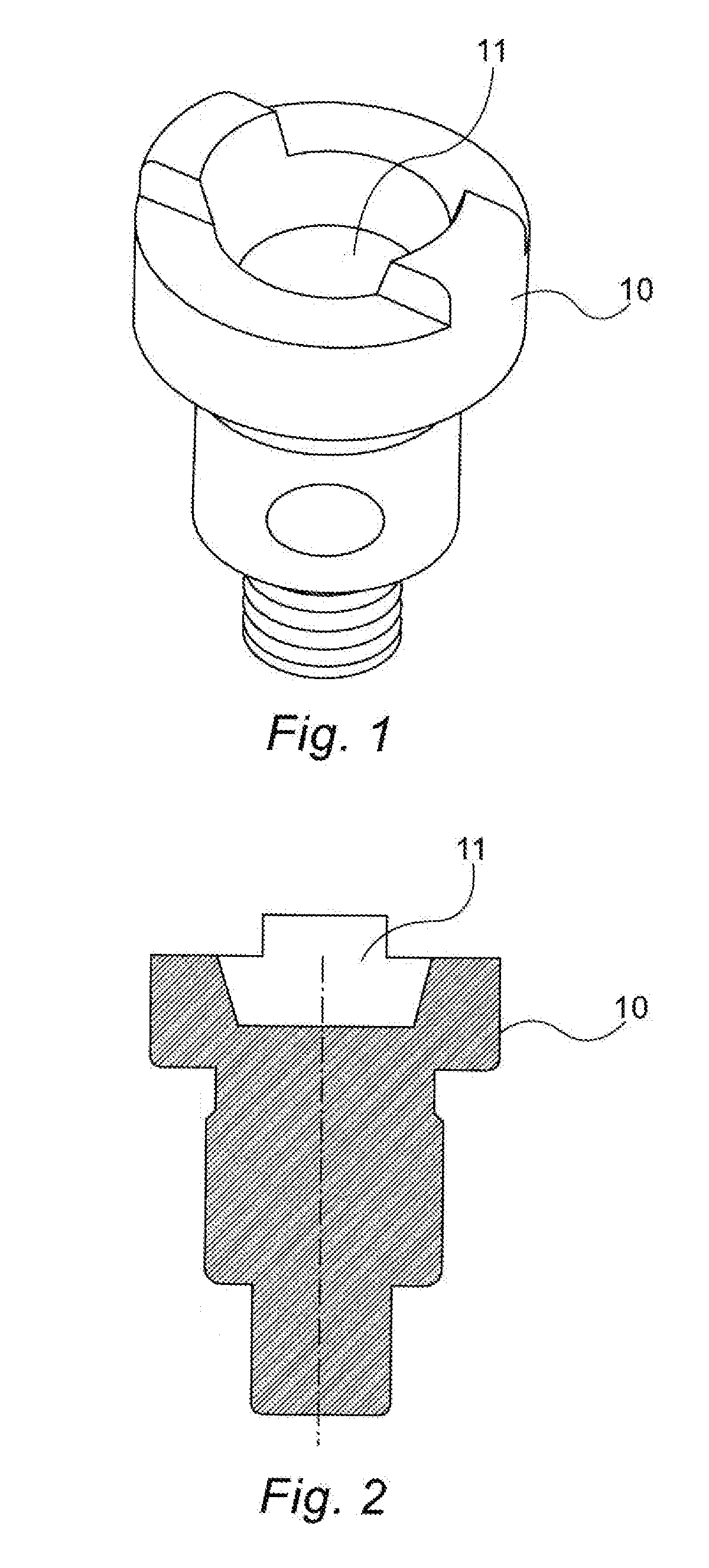
[0038]Reference is first made to FIGS. 1 to 3 which show a shape transfer cap used to determine intraorally the positioning and orientation of a dental implant fixed in a jawbone. For that purpose, the shape transfer cap is inserted in a corresponding dental implant in the mouth of a patient.

[0039]FIG. 1 shows a schematic isometric view of an example of a non-engaging shape transfer cap 10 of the type described in the present disclosure, having a negative depression in its upper surface 11, so that its negative in the impression will have a positive protruding feature, making it more accurate to scan.

[0040]FIG. 2 shows a cross sectional drawing of the shape transfer cap 10 of FIG. 1, showing the negative depression 11 in the top surface.

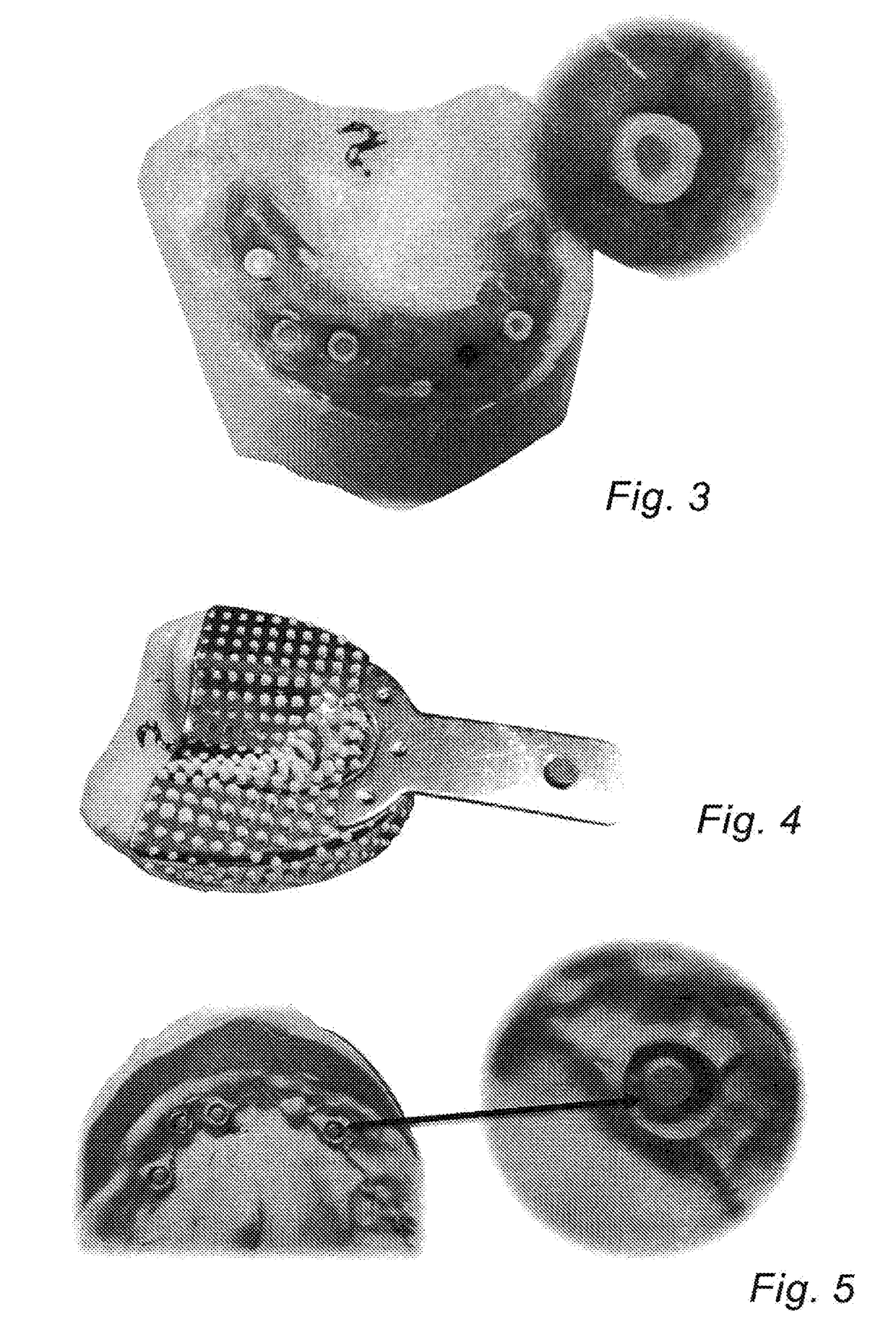
[0041]FIG. 3 shows an example of a patient's mouth with multiple shape transfer caps fitted.

[0042]A closed tray impression is then taken as illustrated schematically in FIGS. 4 and 5. FIG. 4 shows a closed tray impression. FIG. 5 is a photograph show...


PUM


Abstract

A method and device for generating an accurate model of the position of a dental implant in an intraoral cavity, by using a novel shape transfer cap for attachment to the dental implant, the shape transfer cap having a negative depression or a hollow in its end remote from the end by which it is attached to the implant. Such a negative depression forms a positive protrusion in the impression generated of the patient's intraoral cavity with the shape transfer cap. The impression is scanned in order to obtain the computer model for preparing the dental prosthesis for attachment to said implant, including the position and orientation of the implant within the intraoral cavity. The advantage of such a positive protrusion is that it can be more accurately scanned than a depression, which would be formed in the impression if a conventionally shaped transfer cap were used.

Description

BACKGROUND OF INVENTION[0001]The construction of a dental superstructure with passive fitness, i.e. a superstructure without the need for positive screw attachments or the like, is one of the main objectives during implant-based prosthesis preparation. However, because of the high level of fit accuracy required, failure to achieve accurate passive fitness will incur stress on implants which can finally lead to fracture of the implant components and failure of the treatment. The forces created in the implant due to inaccuracies in the superstructure is even able to degrade the bone surrounding the implant and may cause ischemia within the peri-implant tissue, and prevention of subsequent healing. Non-mineral tissue may be formed around the implant, possibly resulting in mechanical damage to the bone, loosening of the implant components and fracture of the restoration. Impression techniques to obtain maximum accuracy of the implant position is thus of great importance. A degree of ina...

Claims


Application Information

Patent Timeline
IPC IPC(8): A61C8/00A61C9/00
CPCA61C8/0001A61C9/0053A61C9/0006A61C13/0004
Inventor ENTELIS, ALEXANDERGOLDSTEIN, MOSHESILVERMAN, REUVEN
Owner OPHIR OPTRONICS SOLUTIONS
Why Eureka
Try Eureka