Vibration generator moving vibrator by magnetic field generated by coil and holder used in vibration-generator

a technology of vibration generator and magnetic field, which is applied in the direction of mechanical vibration separation, dynamo-electric machines, and magnetic circuit shape/form/construction, etc., can solve the problems of increasing the complexity of the structure of the portion in which the plate spring is attached to the chassis side, and increasing the number of components

Active Publication Date: 2013-03-28
MINEBEAMITSUMI INC
View PDF20 Cites 37 Cited by
  • Summary
  • Abstract
  • Description
  • Claims
  • Application Information

AI Technical Summary

Problems solved by technology

Therefore, a structure of a portion in which the plate spring is attached onto the chassis side becomes complicated.
Therefore, an assembly man-hour of the vibration generator increases, and the number of components also increases, which increases a production cost of the vibration generator.
The problem becomes more prominent with increasing demand for downsizing and a low profile of the vibration generator.
That is, because the downsizing of the component advances with the downsizing of the vibration generator, it is necessary to adopt attachment methods, such as spot welding, instead of screw clamp or caulking, and the structure of the attachment portion between the components becomes complicated.
For example, in the case that the spot welding is perfo

Method used


Image

  • Vibration generator moving vibrator by magnetic field generated by coil and holder used in vibration-generator
  • Vibration generator moving vibrator by magnetic field generated by coil and holder used in vibration-generator
  • Vibration generator moving vibrator by magnetic field generated by coil and holder used in vibration-generator

Examples


first embodiment

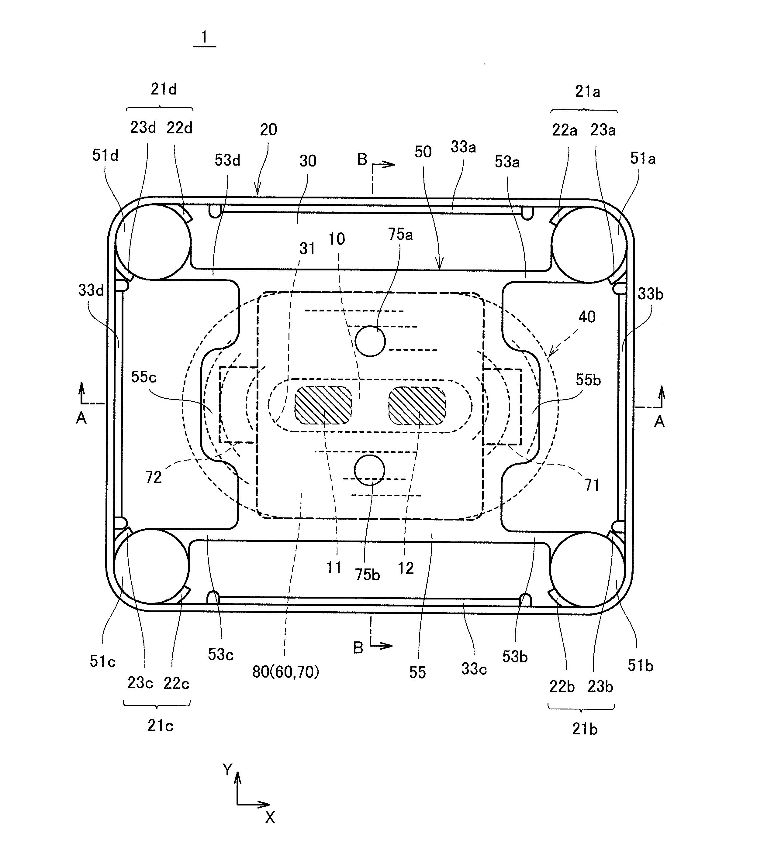
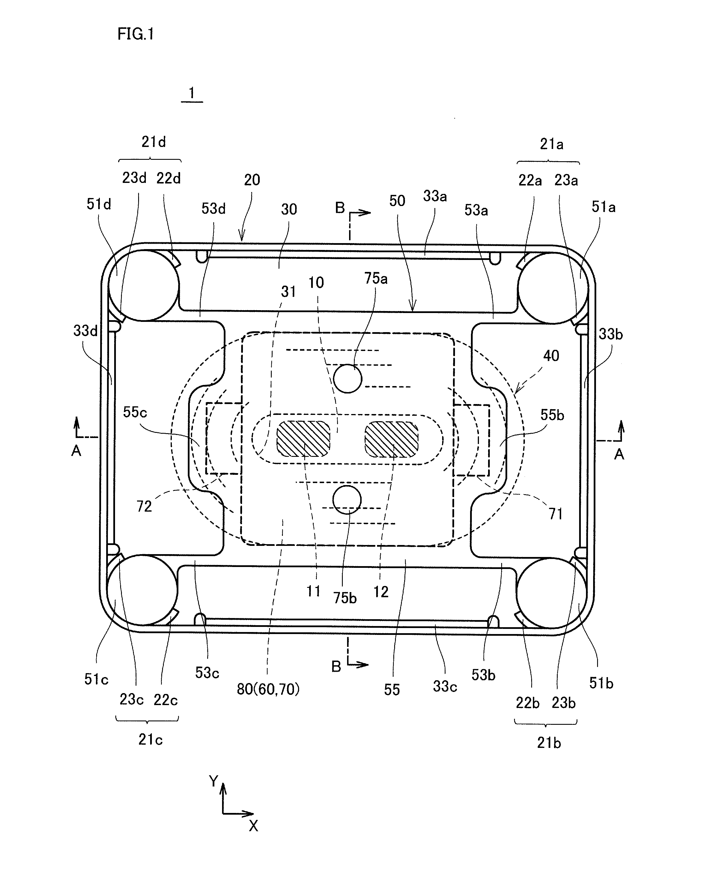
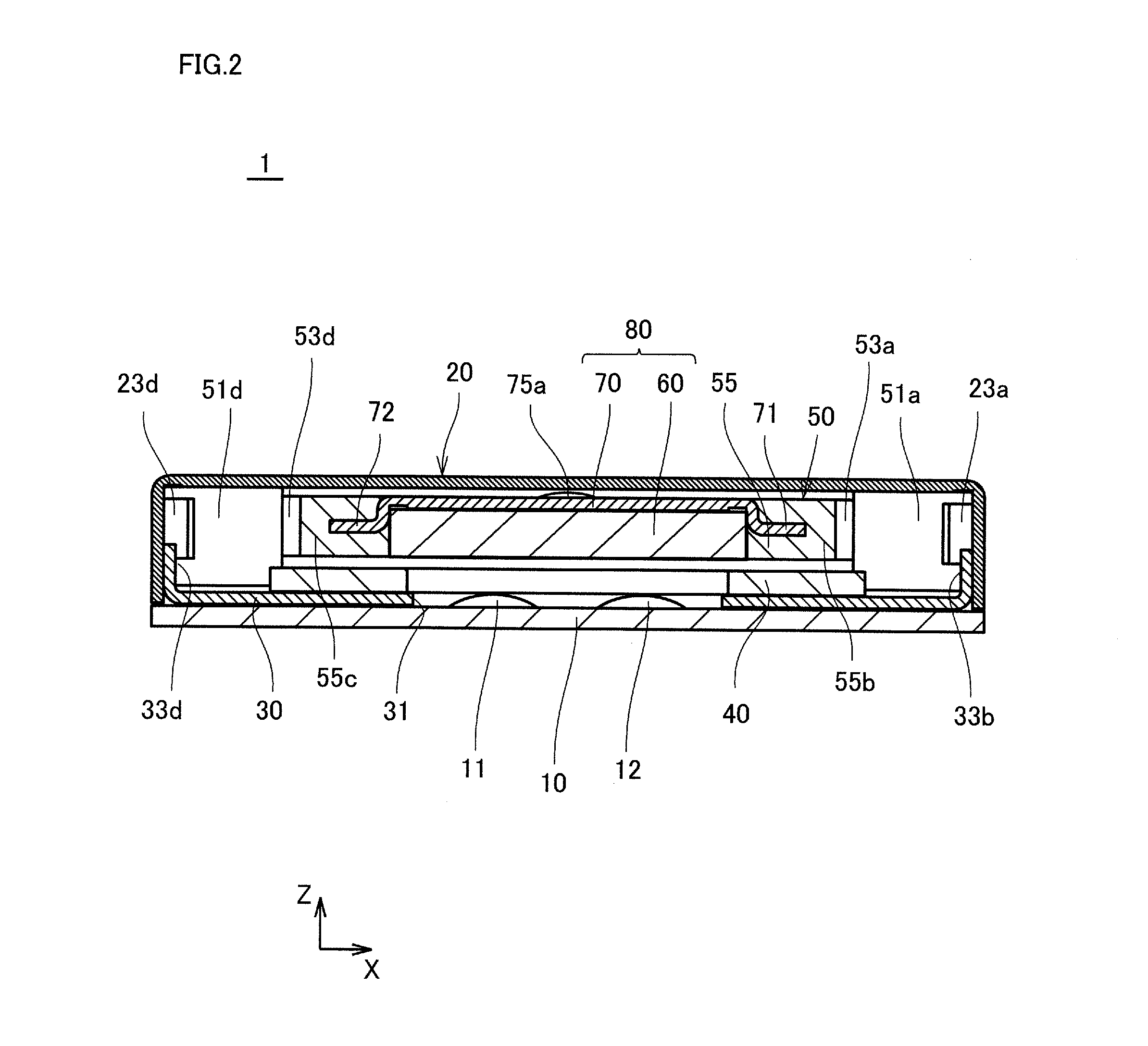
[0059]FIG. 1 is a plan view illustrating a vibration generator according to a first embodiment of the present invention. FIG. 2 is a sectional view taken on a line A-A of FIG. 1.

[0060]In FIG. 1, a holder 50 and the like, which are originally hidden behind an upper surface of a frame 20, are partially illustrated by a solid line for the purpose of easy understanding of a component layout in a vibration generator 1.

[0061]In the following description, with respect to vibration generator 1, sometimes an X-axis direction of an coordinate in FIG. 1 is referred to as a crosswise direction (a positive direction of an X-axis is a right direction when viewed from an origin), and a Y-axis direction is referred to as a front-back direction (a positive direction of a Y-axis is backward when viewed from the origin). Sometimes a Z-axis direction (direction perpendicular to an XY-plane in FIG. 1) in FIG. 2 is referred to as a vertical direction (a positive direction of a Z-axis is upward when viewe...

second embodiment

[0110]Because a basic configuration of a vibration generator according to a second embodiment is identical to that of the first embodiment, the repetitive description is omitted, The second embodiment differs mainly from the first embodiment in that the vibrator includes a weight and a flexible printed board.

[0111]FIG. 7 is a plan view illustrating a vibration generator 201 of the second embodiment. FIG. 8 is a sectional view taken on a line E-E of FIG. 7.

[0112]In FIG. 7, similarly to FIG. 1, a holder 250 and the like, which are originally hidden behind upper surface of frame 20, are partially illustrated by the solid line. A board 210 (illustrated in FIG. 8) is not illustrated in FIG. 7.

[0113]The structure of vibration generator 1 differs mainly from that of vibration generator 1 of the first embodiment in the following two points. That is, vibration generator 201 includes holder 250 instead of holder 50, and includes board 210 instead of double-side board 10. Board 210 has a struc...

third embodiment

[0133]Because a basic configuration of a vibration generator according to a third embodiment is identical to that of the first embodiment, the repetitive description is omitted. The third embodiment differs mainly from the first and second embodiments in that plural coils are provided.

[0134]FIG. 14 is a plan view illustrating a vibration generator 401 according to a third embodiment. FIG. 15 is a sectional view taken on a line G-G of FIG. 14.

[0135]In FIG. 14, similarly to FIG. 1, a holder 450 and the like, which are originally hidden behind upper surface of frame 20, are partially illustrated by the solid line. A structure in which four pillar bodies 51 of holder 450 are retained by frame 20 is not illustrated in FIG. 14. In the third embodiment, the structure in which holder 450 is retained by frame 20 is identical to that of the first embodiment.

[0136]A vibration generator 401 of the third embodiment differs from vibration generator 1 of the first embodiment in that vibration gene...


PUM


Abstract

A holder is used while attached to a chassis of a vibration generator that moves a vibrator to generate a vibration. The holder includes a vibrator retention unit retaining the vibrator, a fixed unit fixed to the chassis, and an arm. The arm connects the fixed unit and the vibrator retention unit, and the arm supports the vibrator retention unit while the vibrator retention unit can be displaced with respect to the fixed unit. The fixed unit, the arm, and the vibrator retention unit are integrally formed using resin.

Description

[0001]This application is based on Japanese Patent Application No. 2011-207335, No. 2012-028847, No. 2012-028848, No. 2012-130712, and No. 2012-130758 filed with the Japan Patent Office on Sep. 22, 2011, Feb. 13, 2012, Feb. 13, 2012, Jun. 8, 2012, and Jun. 8, 2012 respectively, the entire content of which is hereby incorporated by reference.BACKGROUND OF THE INVENTION[0002]1. Field of the Invention[0003]The present invention relates to a holder and a vibration generator, particularly to a holder, which is used in a vibration generator that moves a vibrator to generate a vibration by passage of a current through a coil, and the vibration generator.[0004]2. Description of the Related Art[0005]Various vibration generators having a structure, in which a vibrator including a magnet is supported by a chassis with a spring unit interposed therebetween, are used as the vibration generator that moves the vibrator to generate the vibration. This kind of vibration generator includes a coil, wh...

Claims


Application Information

Patent Timeline
IPC IPC(8): H02K7/065
CPCH02K33/00H02K5/24H02K5/04H02K7/065B06B1/045H02K1/06H02K1/34H02K5/02H02K33/02
Inventor KURODA, MINORUTANAKA, MAKOTO
Owner MINEBEAMITSUMI INC
Why Eureka
Try Eureka