Transducer structure for a transducer probe and methods of fabricating same

a technology of transducer probe and transducer, which is applied in the field of transducer structure, can solve the problems of limiting the design space of the available transducer, limiting the available piezoelectric transducer, and inability to make free-form three-dimensional transducer features, etc., to facilitate forming a plurality of piezoelectric transducer posts, and facilitate minimizing shear waves

Active Publication Date: 2013-03-28
BAKER HUGHES INC
View PDF13 Cites 39 Cited by
  • Summary
  • Abstract
  • Description
  • Claims
  • Application Information

AI Technical Summary

Benefits of technology

[0004]In one aspect, a composite ceramic transducer structure for use in the construction of an ultrasound probe is provided. The structure includes a substrate and a plurality of piezoelectric transducer posts. The plurality of piezoelectric transducer posts are controllably formed on the substrate in a plurality of spatial positions located on an X-Y plane of the substrate. The plurality of piezoelectric posts includes a plurality of shapes defined in an X-Y-Z plane of the substrate, wherein the plurality of piezoelectric transducer posts are configured to facilitate minimizing shear waves within the ultrasound probe.
[0005]In another aspect, a method for manufacturing a ceramic transducer structure for use in the construction of an ultrasound probe is provided. The method includes forming a substrate layer and forming a layer on the substrate layer, wherein the layer includes a transducer material and a photopolymer. The method further includes exposing a plurality of selected regions of the layer to a programmable light pattern to controllably cure the selected regions of the layer to facilitate forming a plurality of piezoelectric transducer posts. The piezoelectric transducer posts include a plurality of spatial positions located on an X-Y plane of the substrate and having a plurality of shapes in an X-Y-Z plane of the substrate. The piezoelectric transducer posts are configured to facilitate minimizing shear waves and maintaining longitudinal waves within the ultrasound probe.
[0006]Still further in an aspect, an ultrasound probe is provided. The probe includes a substrate and a plurality of piezoelectric transducer posts controllably formed on the substrate. The posts are formed in a plurality of spatial positions on an X-Y plane of the substrate, wherein the plurality of piezoelectric posts includes a plurality of shapes defined in an X-Y-Z plane of the substrate. The plurality of piezoelectric transducer posts are configured to facilitate minimizing shear waves and maintaining longitudinal waves within the ultrasound probe. The probe further includes a filler circumscribed around the piezoelectric transducer posts on the substrate. Electrical contacts are coupled to the plurality of piezoelectric transducer posts to facilitate converting electrical energy into ultrasonic energy.

Problems solved by technology

Known dice-and-fill methods for manufacturing piezoelectric transducers generally reach a resolution limit when columnar posts in the piezoelectric transducers are reduced in size.
Moreover, known methods of manufacturing probes, such as dice-and-fill methods, are limited to the fabrication of straight line kerfs between transducer posts, thereby restricting the available transducer design space, e.g. limits of transducer post arrangements, cross-sectional shapes and the inability to make free-form three-dimensional transducer features.
This operation results in an increase in the dicing time to complete the manufacturing of the transducer.
Moreover, the production yield of the dice-and-fill method for manufacturing high-frequency transducers is generally reduced as compared to the production yield of conventionally manufactured lower-frequency transducers due to the increased likelihood of breakage of the (thinner) piezoelectric posts.
Shear waves result in design constraints for probes and result in acoustical interferences such as ringing in probes.

Method used


Image

  • Transducer structure for a transducer probe and methods of fabricating same
  • Transducer structure for a transducer probe and methods of fabricating same
  • Transducer structure for a transducer probe and methods of fabricating same

Examples


Embodiment Construction

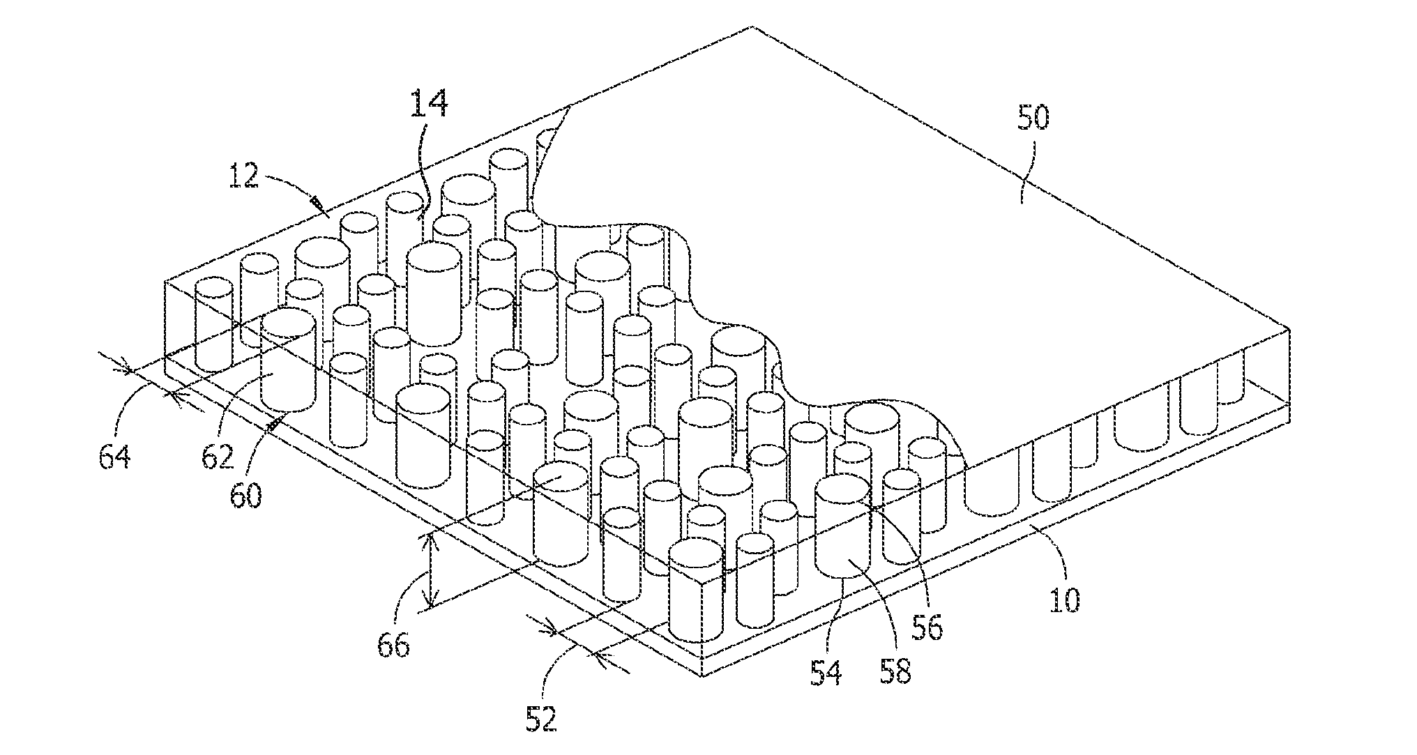
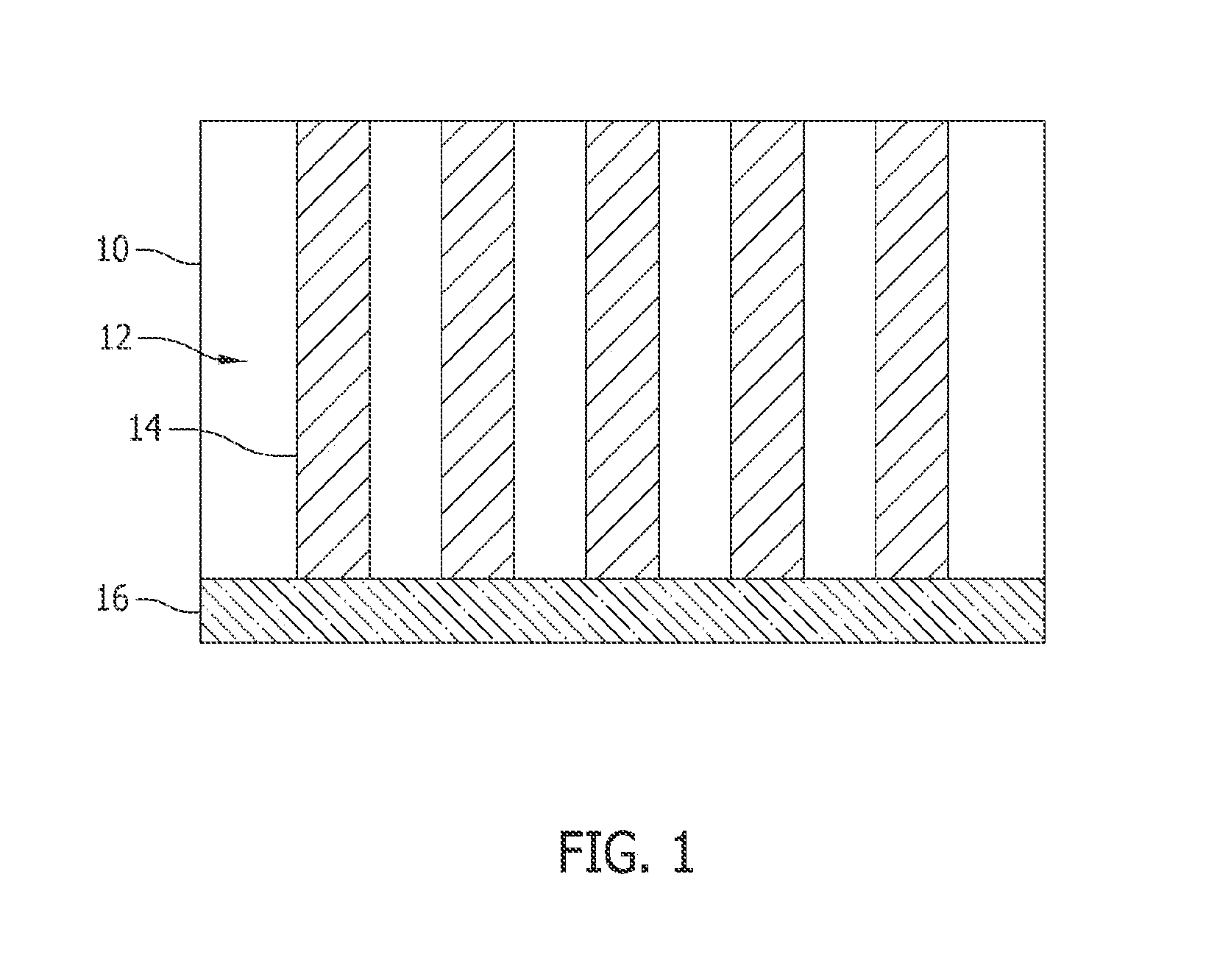
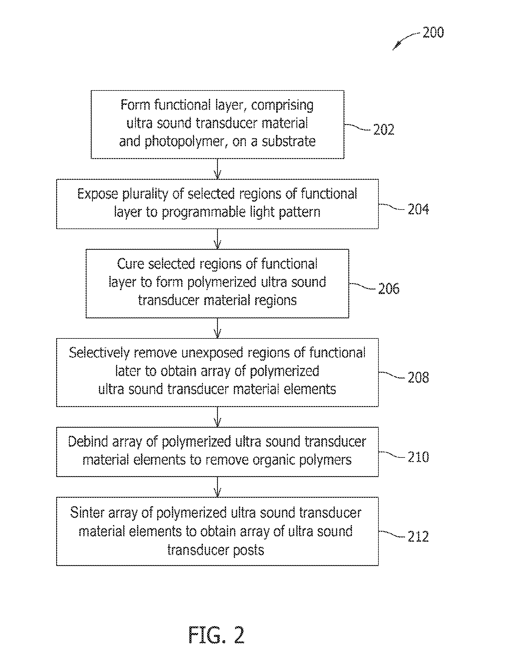
[0022]FIG. 1 illustrates a cross sectional view of an exemplary transducer structure 10 that includes an array 12 of a plurality of transducer posts 14 disposed on a substrate 16. FIG. 2 is a flow chart of an exemplary method 200 that may be used to fabricate array 12 of transducer posts 14. In the exemplary embodiment, method 200 includes forming 202 a layer 18 (shown in FIG. 3) on substrate 16. Substrate 16 may include materials such as, but not limited to, plastic, glass, mica, metals, ceramics, and / or combinations thereof. Layer 18 is fabricated from materials such as, but not limited to, an ultrasound transducer material, and a photo-curable, polymer material. Ultrasound transducer material may include one or more conductive materials, and / or one or more piezoelectric materials and / or one or more acoustic materials.

[0023]In the exemplary embodiment, a plurality of selected regions of layer 18 is exposed 204 to a programmable light system 30 (shown in FIG. 4). Next, selected reg...


PUM

PropertyMeasurementUnit
lengthaaaaaaaaaa
heightaaaaaaaaaa
heightaaaaaaaaaa

Abstract

A composite ceramic transducer structure for use in the construction of an ultrasound probe includes a substrate and a plurality of piezoelectric transducer posts. The plurality of piezoelectric transducer posts are controllably formed on the substrate in a plurality of spatial positions located on an X-Y plane of the substrate. The plurality of piezoelectric posts includes a plurality of shapes defined in an X-Y-Z plane of the substrate, wherein the plurality of piezoelectric transducer posts are configured to facilitate minimizing shear waves within the ultrasound probe.

Description

BACKGROUND OF THE INVENTION[0001]The embodiments described herein relate to transducer structures, and more particularly, to methods and systems for a controlled formation and arrangement of a transducer structure for use in transducer probes.[0002]Ultrasonic probes, which often include a piezoelectric post or an array of piezoelectric posts, are used in several applications, including the nondestructive imaging of the interior of structures by, for instance, ultrasound scanning. In many such imaging applications, it is desirable to use a composite material, which is usually comprised of a piezoelectric material and a non piezoelectric material. These composite materials result in better piezoelectric performance as compared to monolithic piezoelectric materials. It is necessary to reduce the size of the individual piezoelectric features, which constitute the composite, as much as possible, to enable operation at higher frequencies, which in turn provides increased resolution in the...

Claims


Application Information

Patent Timeline
Patent Type & Authority Applications(United States)
IPC IPC(8): H01L41/04H04R17/00H01L41/187
CPCG01N29/245H01L41/37H01L41/183Y10T29/49002Y10T29/42Y10T29/49005B06B1/0622H10N30/852H10N30/092
Inventor KROHN, MATTHEW HARVEYSINGH, PRABHJOTMEYER, PAUL ALOYSIUSLUO, WEI
Owner BAKER HUGHES INC
Why Eureka
Try Eureka