Positioning and Binding Buckle

a technology of buckles and buckles, applied in the direction of snap fasteners, press-button fasteners, transportation items, etc., can solve the problems of higher material cost and manufacturing cost of casting the main body, and achieve the effects of saving metal material consumption, improving structure, and simplifying manufacturing process

Inactive Publication Date: 2013-04-04
LU JUNG WEN
View PDF14 Cites 47 Cited by
  • Summary
  • Abstract
  • Description
  • Claims
  • Application Information

AI Technical Summary

Benefits of technology

[0004]Therefore, it is a primary objective of the present invention to overcome the problems of the prior art by providing a positioning and binding buckle with an improved structure to save the consumption of metal materials and simplify the manufacturing process, so as to reduce the manufacturing cost.

Problems solved by technology

In general, the main body 90 of the conventional buckle structure of this sort is made of metal, and the main body 90 is a solid structure, and thus incurring a higher material cost and a higher manufacturing cost for casting the main body 90.

Method used


Image

  • Positioning and Binding Buckle
  • Positioning and Binding Buckle
  • Positioning and Binding Buckle

Examples


Embodiment Construction

[0018]With reference to FIGS. 1 to 6, embodiments are provided for the purpose of illustrating the present invention only, but not intended for limiting the scope of the present invention.

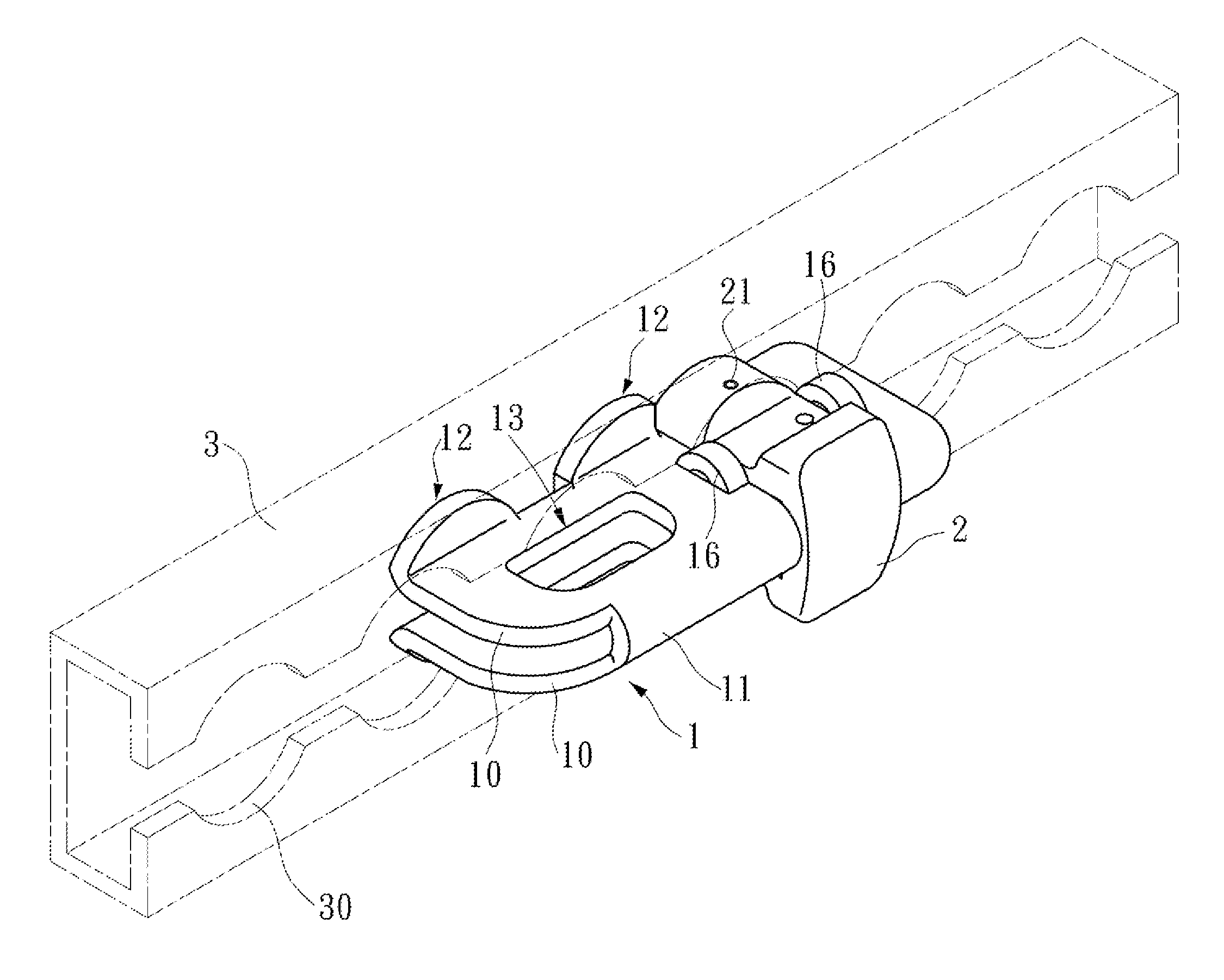
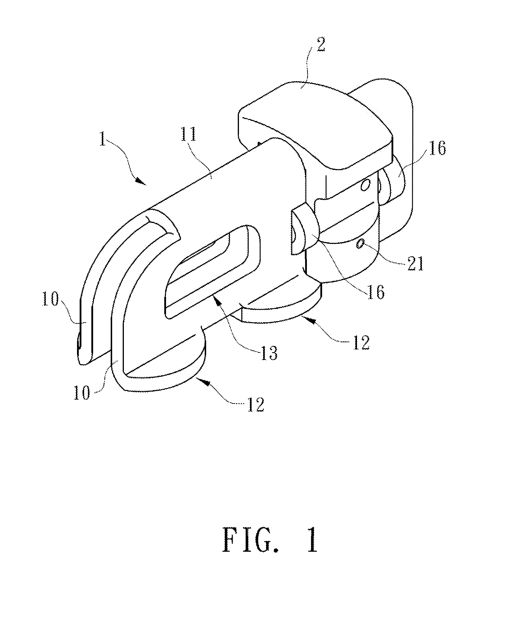
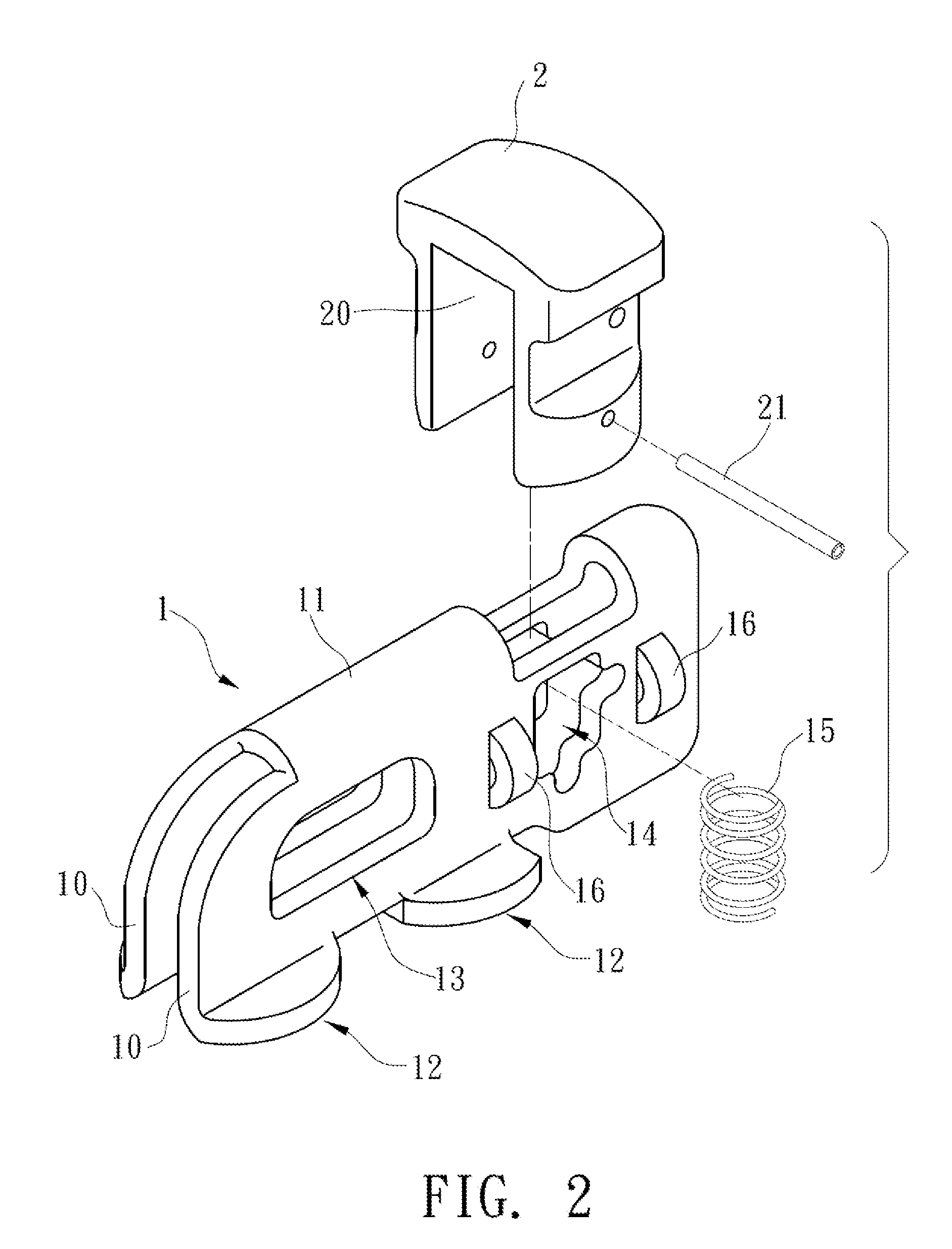
[0019]In a preferred embodiment, a positioning and binding buckle as shown in FIGS. 1 to 3 comprises a main body 1 and a positioning element 2.

[0020]Before the main body 1 is bent and formed, a plate 1A as shown in FIG. 4 is provided, and the plate 1A is pre-cut according to a predetermined shape of the buckle. In FIGS. 1 and 2, the main body 1 is formed by bending the plate 1A into two parallel side plates 10 and the top of the side plates 10 is coupled by a connecting portion 11, Since the main body 1 is formed by bending the plate 1A, therefore a hollow is formed between the two side plates 10, and the bottoms of the two side plates 10 are folded sideway respectively to form two stop portions 12, wherein a gap is formed between the two stop portions 12, and the two side plates 10 have a buckle h...


PUM


Abstract

A positioning and binding buckle includes a main body and a positioning element, and the main body is formed by bending a plate to form two side plates and a connecting portion, and a hollow is formed between the two side plates and two stop portions are formed at the bottom of the two side plates and passed through a buckle hole a containing hole containing a compression spring, and positioning element is disposed across the two side plates by its cut groove and limited between at least two opposite lugs, and the positioning element is passed through the containing hole by an insert pin and pushed by the bottom edge of the compression spring, and the positioning element can be lifted towards the connecting portion and pushed back by the compression spring, such that the bottom is aligned evenly with the stop portion.

Description

FIELD OF THE INVENTION[0001]The present invention relates to a buckle structure, in particular to the buckle structure capable of positioning and binding goods.BACKGROUND OF THE INVENTION[0002]With reference to FIG. 9 for a conventional buckle structure for binding goods, the conventional buckle structure comprises a main body 90 having a buckle hole 91, two stop portions 92 disposed at the bottom of the main body, and a positioning element 93 disposed across the main body 90 and provided for lifting the main body 90 and returning to its original position automatically after being released. When the buckle structure is used, the positioning element 93 is lifted to install the two stop portions 92 of the main body 90 into two concave holes 95 of a guide rail 94 respectively, and the main body 90 is shifted slightly to dislocate the two stop portions 92 with the concave holes 95. Now, the positioning element 93 is aligned precisely with a concave hole 95 to release the positioning ele...

Claims


Application Information

Patent Timeline
Patent Type & Authority Applications(United States)
IPC IPC(8): A44B11/16
CPCY10T24/45141Y10T24/44017Y10T24/45796Y10T24/45801Y10T24/4773Y10T24/4056B60P7/0815
Inventor LU, JUNG-WEN
Owner LU JUNG WEN
Why Eureka
Try Eureka