Oven Lighting

Inactive Publication Date: 2013-04-04
OSRAM OPTO SEMICON GMBH & CO OHG
View PDF7 Cites 15 Cited by
  • Summary
  • Abstract
  • Description
  • Claims
  • Application Information

AI Technical Summary

Benefits of technology

[0005]It is an object of at least some of the embodiments of the present invention to provide an oven lighting that is distinguished by a reduced difficulty of replacing a

Problems solved by technology

A particular problem for oven lightings is that the heat produced by the oven can deteriorate the function of the lamp.
This makes is particularly difficult to use modern lighting systems such as LED modules for oven lightings.
In particular, the long-term s

Method used


Image

  • Oven Lighting
  • Oven Lighting
  • Oven Lighting

Examples


Example

DETAILED DESCRIPTION OF THE DRAWINGS

[0026]Identical or identically acting constituent parts are provided with the same reference symbols in the figures. The illustrated constituent parts and also the size relationships of the constituent parts with respect to one another should not be regarded as true to scale.

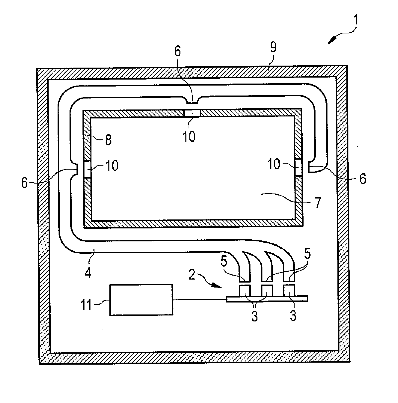
[0027]The oven 1 illustrated in FIG. 1 has a cavity 7 which can be a baking chamber, for example. The oven 1 comprises an oven lighting which uses an LED module 2 as a light source. The LED module 2 preferably has a plurality of LEDs 3. The LEDs 3 can be arranged on a common carrier. For example, the LEDs 3 can be arranged in a row or in an array.

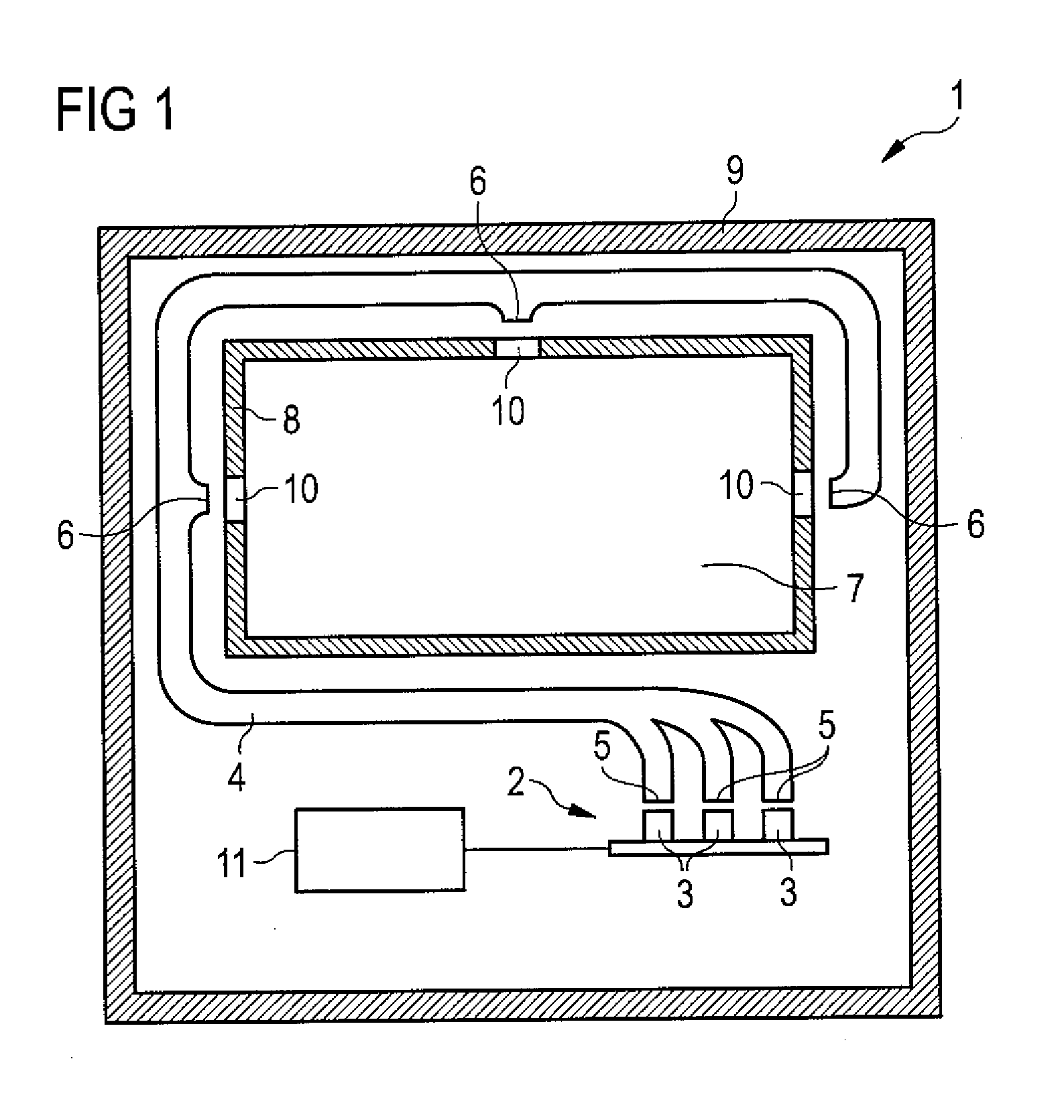
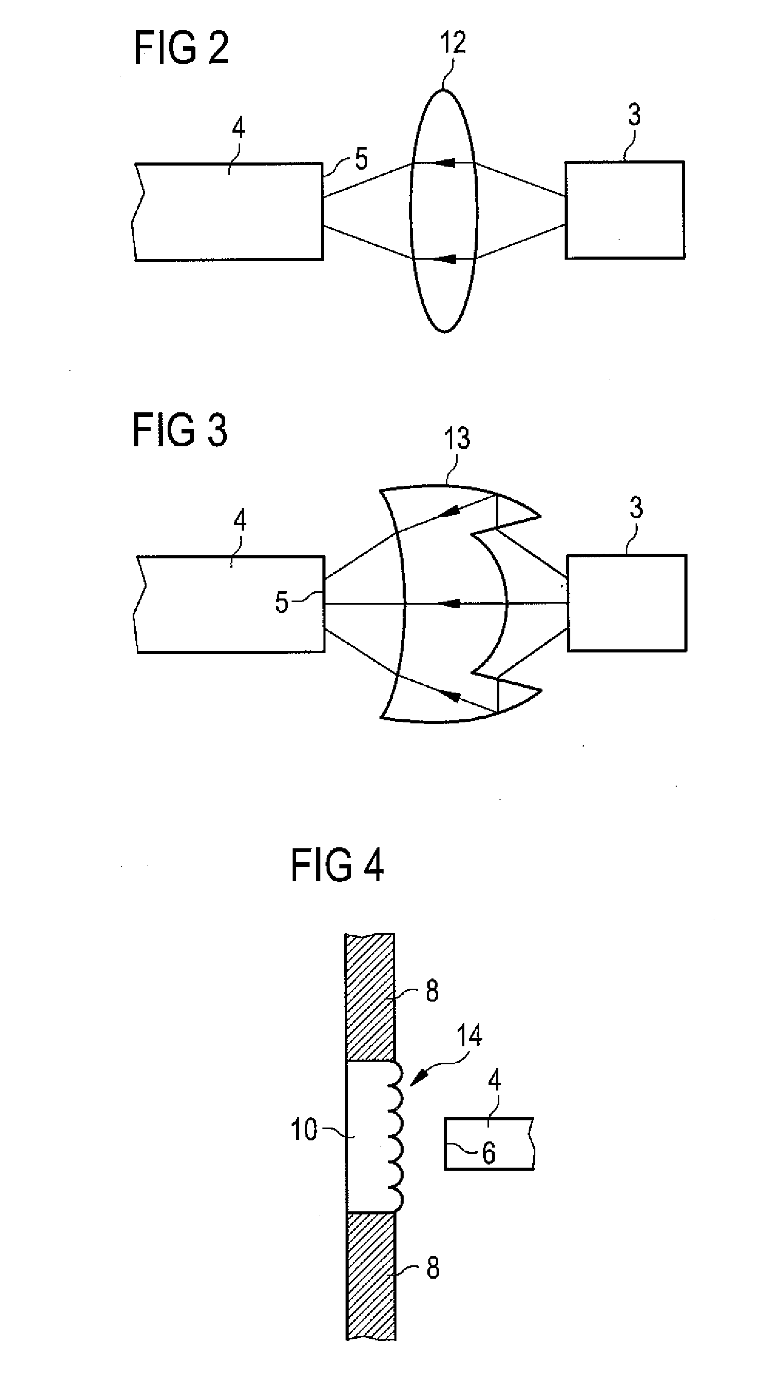
[0028]The light emitted by the LEDs 3 is coupled in into a plurality of light input ends 5 of an optical fiber bundle 4. The optical fiber bundle 4 acts as a light guide which guides the light to a plurality of light output ends 6 of the optical fiber bundle 4. The light output ends 6 are arranged adjacent to a cavity wall 8 of the ov...


PUM

PropertyMeasurementUnit
Temperatureaaaaaaaaaa
Coloraaaaaaaaaa
Transparencyaaaaaaaaaa

Abstract

An oven lighting which comprises an LED module with at least one LED and an optical fiber bundle. The optical fiber bundle has at least one light input end adjacent to the LED module and at least one light output end adjacent to a cavity wall of an oven cavity for illuminating the oven cavity.

Description

FIELD OF THE INVENTION[0001]The invention concerns an oven lighting and an oven comprising the oven lighting.BACKGROUND OF THE INVENTION[0002]An oven, in particular a baking oven for household applications, is typically provided with an oven lighting for illuminating the interior of the baking chamber. Usually, incandescent lamps with a glass bulb are used as light sources for oven lightings. A particular problem for oven lightings is that the heat produced by the oven can deteriorate the function of the lamp. This makes is particularly difficult to use modern lighting systems such as LED modules for oven lightings. In particular, the long-term stability of LEDs can be severely reduced by the heat and the temperature changes caused by the oven.[0003]An oven lighting is disclosed in the document EP 2 233 839 A1. This document suggests using a glass lens comprising a cavity for reducing heat conduction towards the light source.[0004]The arrangement of the light source behind a thick g...

Claims


Application Information

Patent Timeline
IPC IPC(8): F24C15/00G02B6/10G05D25/00F21V8/00
CPCF24C15/008G02B6/0006G02B6/0008F21V2200/10F21W2131/307F21Y2101/02G02B6/04F21Y2115/10
Inventor EICHELBERGER, CHRISTOPHER L.SCHNEIDER, GARY
Owner OSRAM OPTO SEMICON GMBH & CO OHG
Why Eureka
Try Eureka