
Method And Apparatus For Automatic Positioning Of Gull Wings Of Stackerbar Planter Based On Tractor Hitch Position

a technology of automatic positioning and stackerbar planter, which is applied in the field of automatic positioning of gull wings of stackerbar planter based on tractor hitch position, and can solve the problems of wing sections, drawbacks of larger seed boxes, and increase the overall weight of openers

Active Publication Date: 2013-04-04
CNH IND CANADA
View PDF1 Cites 5 Cited by
  • Summary
  • Abstract
  • Description
  • Claims
  • Application Information

AI Technical Summary

Benefits of technology

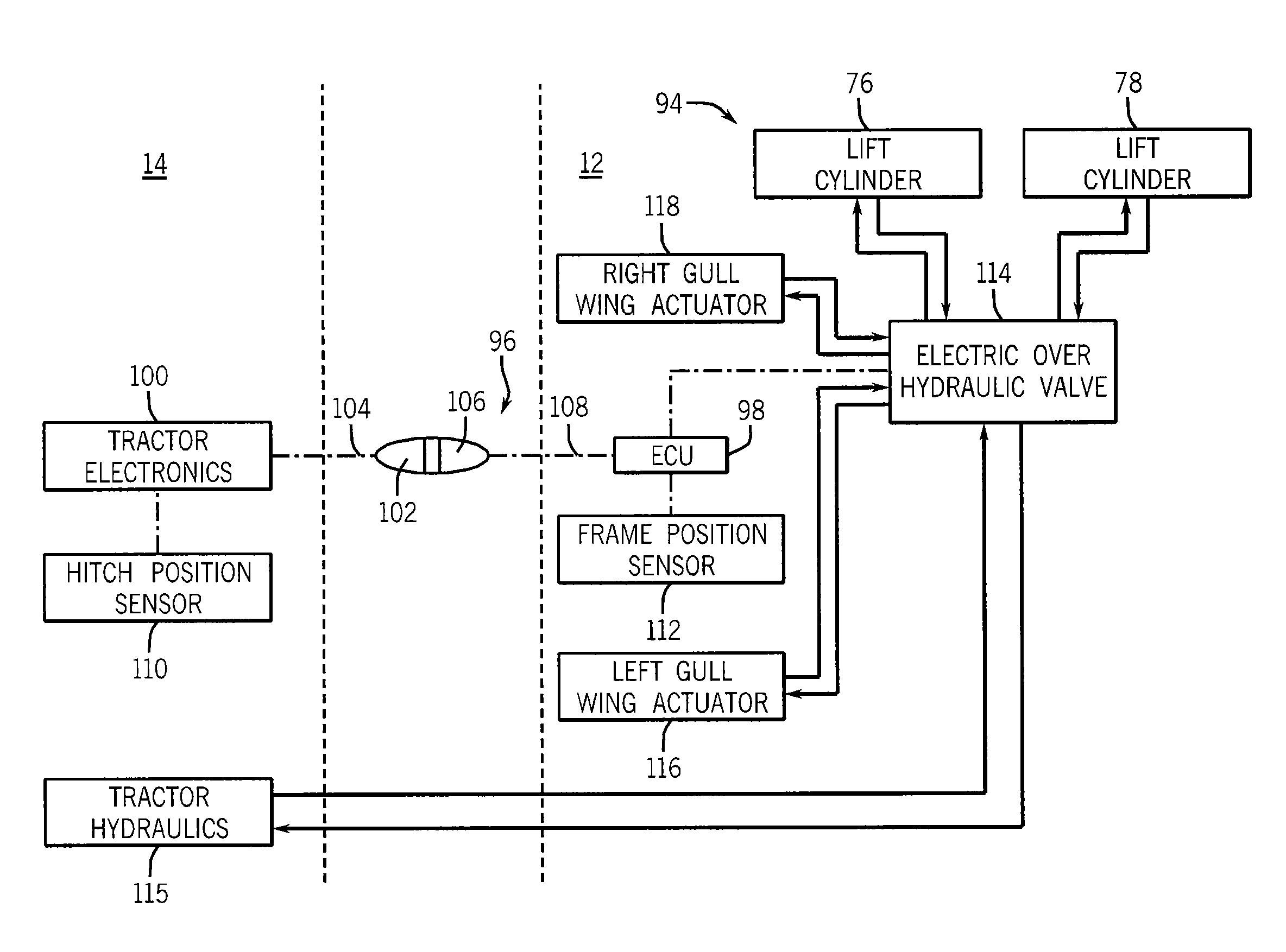
The present invention is a method and device that automates tasks at headland turns or similar events by controlling the position of the tractor hitch to which the implement is connected. This means that the operator can control the position of the implement by raising and lowering the tractor hitch using a remote control. The invention allows the planter to automatically control the operation of the implement based on the position of the tractor hitch without needing further input from the operator.

Problems solved by technology

Larger seed boxes, however, have drawbacks.
The additional material that can be carried by larger seed boxes adds to the overall weight of the openers, including those mounted to the wing sections.
This additional weight can stress the lifting / lowering system that stacks the wing sections, or require a more robust system, which can add to the overall size, mass, complexity, and cost of the implement.
Further, it can be problematic and time consuming to individually fill each of the seed boxes, whether using bags or a conveyor system.
Raising the gull wings and the frame for the bulk fill hopper(s) at headland turns poses one of the challenges that is faced by an operator when making a headland turn onto a new swath.
By requiring the operator to perform these tasks substantially simultaneously, the operator can become mentally and physically fatigued, require an enhanced skill level to operate the stack-fold planter, increase the likelihood that the operator may make an error, or reduce the performance of the stack-fold planter at headland turns.

Method used


Image

  • Method And Apparatus For Automatic Positioning Of Gull Wings Of Stackerbar Planter Based On Tractor Hitch Position
  • Method And Apparatus For Automatic Positioning Of Gull Wings Of Stackerbar Planter Based On Tractor Hitch Position
  • Method And Apparatus For Automatic Positioning Of Gull Wings Of Stackerbar Planter Based On Tractor Hitch Position

Examples


Embodiment Construction

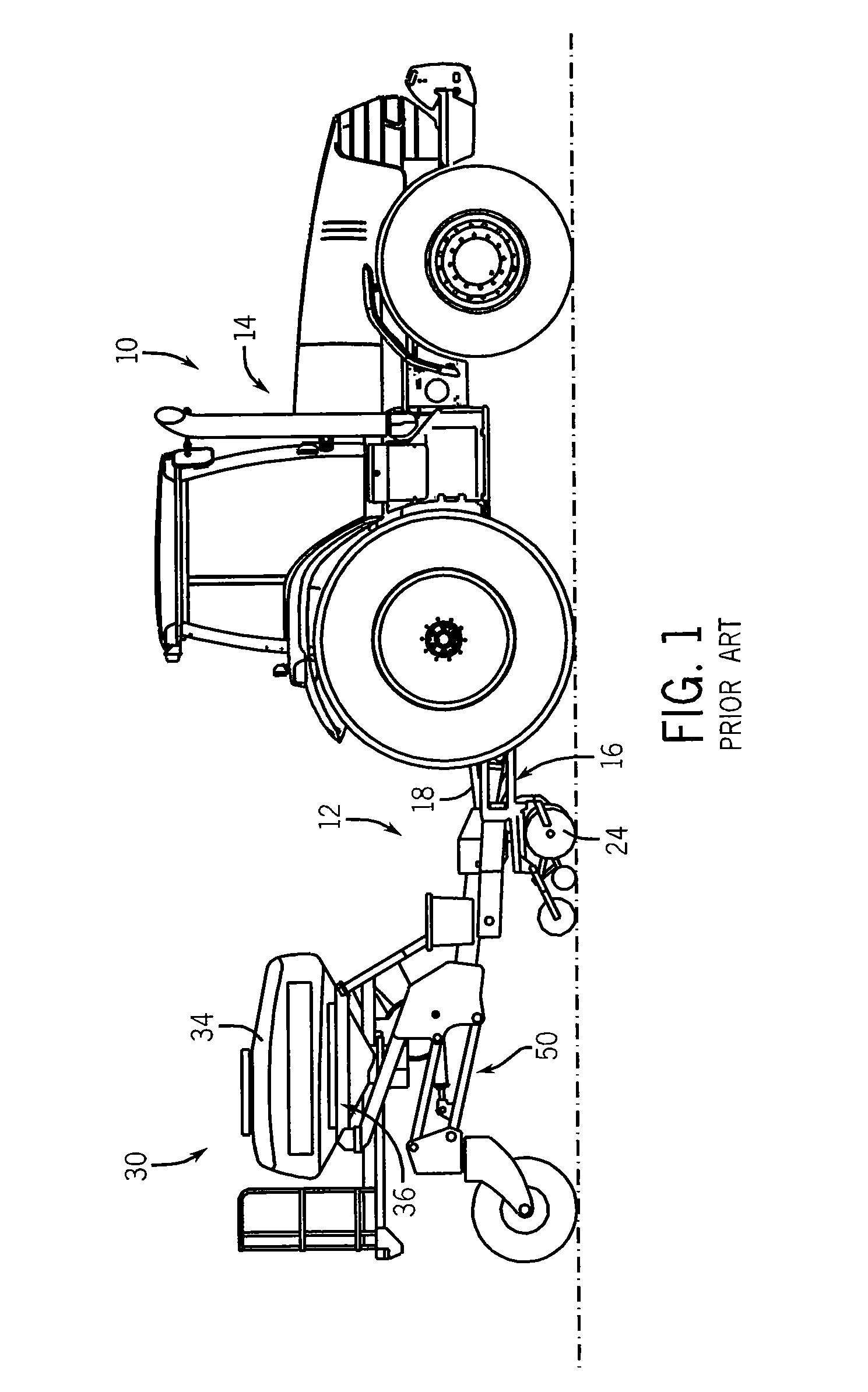
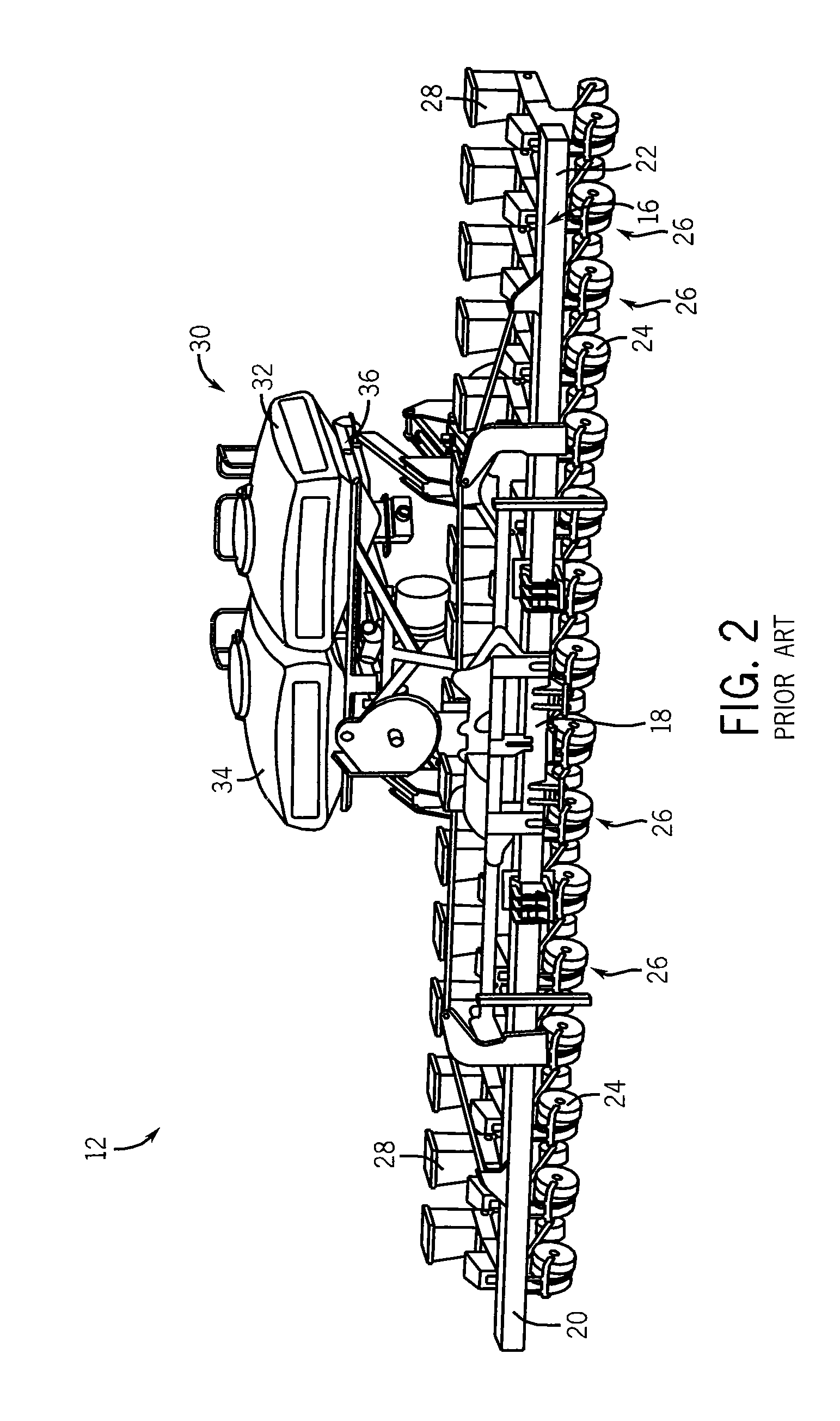
[0020]As will be made apparent from the following description, the present invention provides an apparatus that automatically adjusts the position of an implement in response to changes in the position of the hitch of a tractor towing the implement. For purposes of description, the invention will be described with respect to a stack-fold planter, such as that shown in FIGS. 1-4, but it is understood that the invention is applicable with other types of implements. The invention, which can also be embodied in an automated method, is designed to reduce the number of user inputs that were heretofore required to command movements of the implement, such as at headland turns.

[0021]Turning now to FIGS. 1-4, a planting system 10 includes a stack-fold implement 12, shown in a field working position, coupled to a prime mover 14, e.g., tractor, in a known manner. For purposes of illustration, the stack-fold implement 12 is a row crop planter, which as shown in FIG. 2, includes a frame 16 genera...


PUM


Abstract

A method and apparatus for automating some of the tasks that heretofore required operator action at headland turns or similar events are provided. The present invention automates operation of lift assist wheels and / or gull wings, such as those found on a stack-fold implement, based on the position of the tractor hitch to which the implement is coupled. An operator may control the position of the implement, such as at a headland turn, by raising and lowering the tractor hitch using a remote control. The invention enables the planter to compare the tractor hitch position relative to an implement position and control operation of the implement accordingly without additional user inputs.

Description

BACKGROUND OF THE INVENTION[0001]The present invention is generally directed to farm implements and, more particularly, to a method and apparatus for automatic positioning wing sections of a foldable farm implement.[0002]Increasingly, farm implements have been designed to have frames that can be folded between field-working and transport positions. One such type of farm implement is a stack-fold planter, such as the 1230 Stackerbar planter from Case New Holland, LLC. Stack-fold planters generally consist of a center frame section and a pair of wing frame sections. In the field-working position, the wing frame sections are evenly aligned with the center frame section. In the transport position, however, the wing sections are lifted to a position directly above the center frame section, i.e., to a “stacked” position. In the stacked position, the width of the implement is generally that of the center frame section, thus making the implement better suited for transport along roads and b...

Claims


Application Information

Patent Timeline
IPC IPC(8): A01B63/22
CPCA01B63/22A01B73/02A01C7/208A01B73/044
Inventor TUTTLE, THOMASREMOUE, TYLER
Owner CNH IND CANADA
Learn More