
Overhead scanner device, image processing method, and computer-readable recording medium

a scanner and image processing technology, applied in the field of overhead scanner devices, image processing methods, and computer-readable recording media, can solve problems such as erroneous detection of points of coordinates that are not those of fingertips that are not intended by users, complicated operation, and inability to apply scanners to cases

Inactive Publication Date: 2013-04-04
PFU LTD
View PDF4 Cites 18 Cited by
  • Summary
  • Abstract
  • Description
  • Claims
  • Application Information

AI Technical Summary

Benefits of technology

The present invention is related to an overhead scanner device and a computer program for controlling it. The device includes an image photographing unit and a control unit. The control unit includes an image acquiring unit that controls the image photographing unit to acquire an image of a document including at least an indicator provided by a user. The control unit also includes a specific-point detecting unit that detects two specific points each determined based on the distance from the gravity center of an indicator to the end of the indicator, from the image acquired by the image acquiring unit. The control unit further includes an image cropping unit that crops the image acquired by the image acquiring unit into a rectangle with opposing corners at the two points detected by the specific-point detecting unit. The technical effect of the invention is to accurately detect the fingertip and to accurately locate the indicator in the image.

Problems solved by technology

However, the conventional scanner devices have some problem that when part of an area is desired to be cropped from a read image, the operation is complicated because the devices require an operation to previously specify an area to be cropped on a console before scanning or require an operation to specify an area to be cropped on an image editor after scanning.
For example, the overhead scanner described in JP-A-H06-105091 has a problem that because only a document area in a sub-scanning direction (lateral direction) is specified although the skin color of the hand is detected to correct an image of the hand included therein, this scanner cannot be applied to a case where part of an area to be cropped is desired to be specified from a read image.
The overhead scanner described in JP-A-H07-162667 has a problem that, because skin color is detected and the innermost pairs of coordinates of the edge of the right and left hands are used as points determined as opposing corners of a rectangle to be cropped, points of coordinates that are not those of fingertips that are not intended by the user may be erroneously detected.
The overhead scanner described in JP-A-H10-327312 has a problem in its operability because a dedicated coordinate input pen has to be used although an image area to be cropped can be specified by the coordinate indicator pen.
The flat-bed type of scanner described in JP-A-2005-167934 has a problem that the operation remains still complicated because although a document size and an offset or the like can be recognized by being pre-scanned by the area sensor, a read image has to be specified using a point pen or the like on editing software in order to specify an area to be cropped.

Method used


Image

  • Overhead scanner device, image processing method, and computer-readable recording medium
  • Overhead scanner device, image processing method, and computer-readable recording medium
  • Overhead scanner device, image processing method, and computer-readable recording medium

Examples


Embodiment Construction

[0036]Embodiments of an overhead scanner device, an image processing method, and a computer-readable recording medium according to the present invention will be explained in detail below based on the drawings. The embodiments do not limit the invention.

1. Configuration of the Embodiment

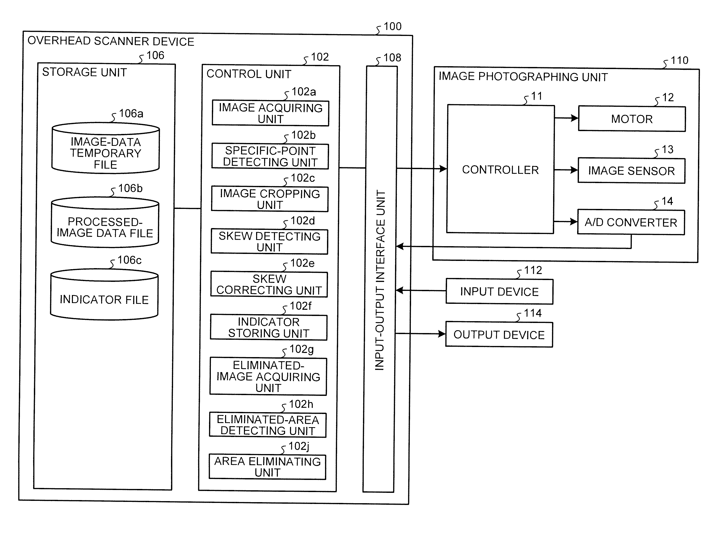
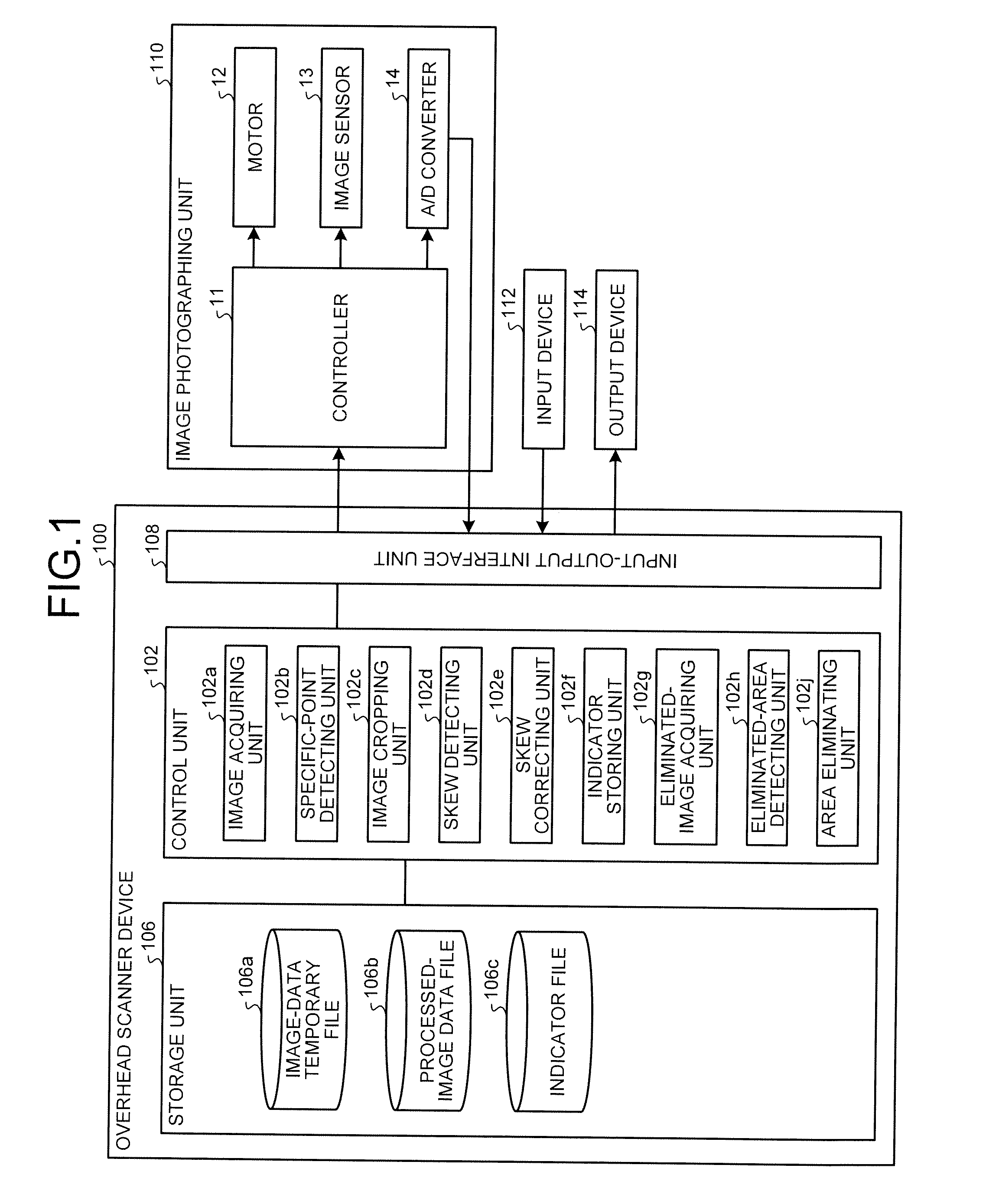
[0037]The configuration of an overhead scanner device 100 according to the present embodiment is explained below with reference to FIG. 1. FIG. 1 is a block diagram of an example of a configuration of the overhead scanner device 100.

[0038]As shown in FIG. 1, the overhead scanner device 100 includes at least an image photographing unit 110 that scans a document placed face-up from above, and a control unit 102. In this embodiment, the overhead scanner device 100 further includes a storage unit 106, and an input-output interface unit 108. Each unit of the overhead scanner device 100 is communicably connected to one another via any communication channels.

[0039]The storage unit 106 stores the various data...


PUM


Abstract

An overhead scanner device includes an image photographing unit, and a control unit, wherein the control unit includes an image acquiring unit that controls the image photographing unit to acquire an image of a document including at least an indicator provided by a user, a specific-point detecting unit that detects two specific points each determined based on the distance from the gravity center of an indicator to the end of the indicator, from the image acquired by the image acquiring unit, and an image cropping unit that crops the image acquired by the image acquiring unit into a rectangle with opposing corners at the two points detected by the specific-point detecting unit.

Description

CROSS-REFERENCE TO RELATED APPLICATION[0001]This application is based upon and claims the benefit of priority from Japanese Patent Application No. 2010-125150, filed May 31, 2010, and PCT application PCT / JP2011 / 060484, filed Apr. 28, 2011, the entire contents of which are incorporated herein by reference.BACKGROUND OF THE INVENTION[0002]1. Field of the Invention[0003]The present invention relates to an overhead scanner device, an image processing method, and a computer-readable recording medium.[0004]2. Description of the Related Art[0005]An overhead scanner in which a document is placed face-up and is photographed from above has been developed.[0006]In order to solve a problem that because the document is pressed by hand, an image of the hand is included in an image of the document, JP-A-H06-105091 discloses an overhead scanner that determines skin color from pixel outputs and corrects a skin color area by replacing it with a white color.[0007]JP-A-H07-162667 discloses an overhead ...

Claims


Application Information

Patent Timeline
Patent Type & Authority Applications(United States)
IPC IPC(8): H04N7/00
CPCG06T11/60H04N1/3873H04N7/002G06T2210/22G06T11/00
Inventor KASAHARA, YUKI
Owner PFU LTD
Learn More