Vehicle lighting unit

a technology for vehicle interior lighting and lighting, which is applied in vehicle interior lighting, transportation and packaging, light and heating equipment, etc., can solve the problems of different brightnesses observed through the lens

Active Publication Date: 2013-04-04
STANLEY ELECTRIC CO LTD
View PDF7 Cites 24 Cited by
  • Summary
  • Abstract
  • Description
  • Claims
  • Application Information

AI Technical Summary

Benefits of technology

[0009]In the vehicle lighting unit configured as above, although the light passing through the second lens is relatively low luminous intensity light, that light can be projected only (or substantially only) in an upward direction with respect to a horizontal plane by the action of the first reflector and the second reflector. This can allow the luminous intensity of light through the first lens and the luminous intensity of light through the second lens to match (or substantially match) when the lenses are viewed from a viewpoint in front of the vehicle. Namely, this can allow the brightnesses observed through the first and second lenses to match (or substantially match) when the lenses are viewed from a viewpoint in front of the vehicle.
[0016]According to the presently disclosed subject matter, a vehicle lighting unit can be provided which allows brightnesses observed through the vertically arranged lenses to match (or substantially match) when the vehicle lighting unit is viewed from a viewpoint in front of the vehicle (a certain viewpoint above the horizontal line).

Problems solved by technology

This causes a problem in that the brightnesses observed through the lenses are different from each other.

Method used


Image

  • Vehicle lighting unit
  • Vehicle lighting unit
  • Vehicle lighting unit

Examples


second exemplary embodiment

[0113]A description will now be made below to a vehicle lighting unit of a second exemplary embodiment with reference to the accompanying drawings.

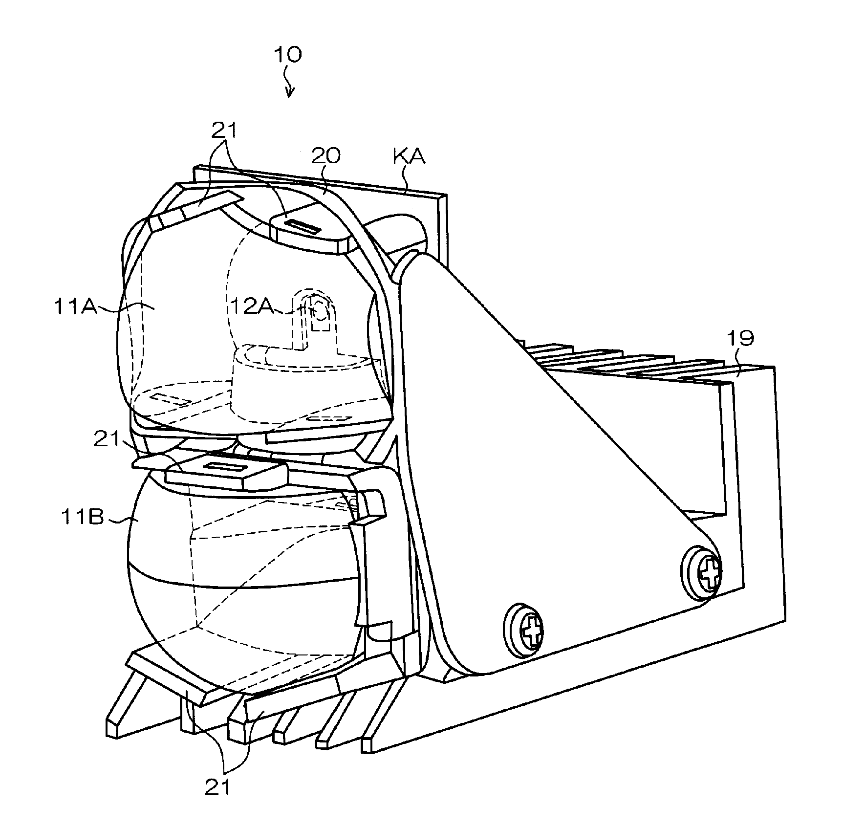
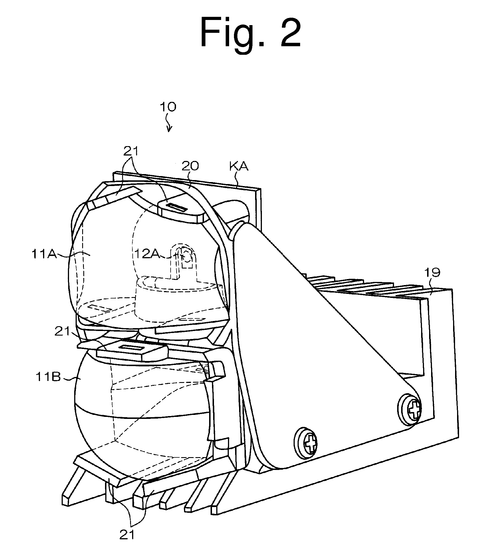
[0114]The vehicle lighting unit 110 of the present exemplary embodiment made in accordance with the principles of the presently disclosed subject matter can form a high-beam light distribution pattern and a low-beam light distribution pattern. At least one vehicle lighting unit 110 of the present exemplary embodiment can be disposed on each of the front left and right sides of a vehicle body such as an automobile.

[0115]FIG. 10 is a vertical cross-sectional view of the vehicle lighting unit 110 taken along a vertical plane including a first optical axis AX111A and a second optical axis AX111B of the vehicle lighting unit 110.

[0116]As shown in FIG. 9, the vehicle lighting unit 110 can include: a first lens 111A having a focal point F111A on a vehicle rear-side; a second lens 111B disposed below the first lens 111A and having a focal point F...


PUM


Abstract

A vehicle lighting unit can include a first lens and a second lens disposed below the first lens, and a first semiconductor light-emitting device disposed substantially at a vehicle rear-side focal point of the first lens. Light emitted from the first semiconductor light-emitting device in a narrow angle direction can be incident on the first lens. A first reflector can be disposed diagonally forward and downward with respect to the first semiconductor light-emitting device such that light emitted from the first semiconductor light-emitting device in a wide angle direction is incident thereon and reflected diagonally rearward and downward. The light emitted in the narrow angle direction and incident on the first lens having a luminous intensity higher than the light emitted in the wide angle direction. A second reflector can be disposed diagonally rearward and downward with respect to the first reflector.

Description

[0001]This application claims the priority benefit under 35 U.S.C. §119 of Japanese Patent Application No. 2011-147615 filed on Jul. 1, 2011, which is hereby incorporated in its entirety by reference.TECHNICAL FIELD[0002]The presently disclosed subject matter relates to a vehicle lighting unit, and particularly to a vehicle lighting unit including vertically arranged lenses.BACKGROUND ART[0003]Vehicle lamps including vertically arranged lenses have been proposed (see, for example, Japanese Patent No. 4666160 or U.S. Pat. No. 7,325,954 corresponding to JP Patent No. 4666160).[0004]As shown in FIG. 1, a vehicle lamp 200 described in Japanese Patent No. 4666160 can include vertically arranged lenses 210A and 210B, an HID bulb 220, an upper reflector 230A, a lower reflector 230B, and the like. In the vehicle lamp 200 configured as described above, upward light emitted from the HID bulb 220 can be reflected by the upper reflector 230A, pass through the upper lens 210A, and then be projec...

Claims


Application Information

Patent Timeline
Patent Type & Authority Applications(United States)
IPC IPC(8): B60Q1/00
CPCB60Q1/0041B60Q2300/45B60Q1/0029F21S48/1159F21S48/1388F21S48/1154F21S41/143F21S41/147F21S41/255F21S41/321F21S41/338F21S43/14F21S43/26F21S43/31F21S43/40F21W2103/55F21S41/365F21W2102/18F21V13/04F21S41/151
Inventor SEKIGUCHI, TATSUYA
Owner STANLEY ELECTRIC CO LTD
Why Eureka
Try Eureka