Method for dynamically modulating driving current of backlight module
- Summary
- Abstract
- Description
- Claims
- Application Information
AI Technical Summary
Benefits of technology
Problems solved by technology
Method used
Image
Examples
first embodiment
The First Embodiment
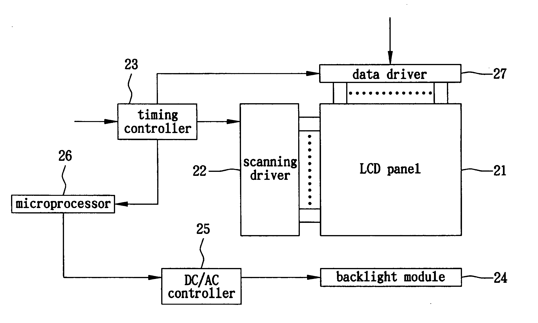
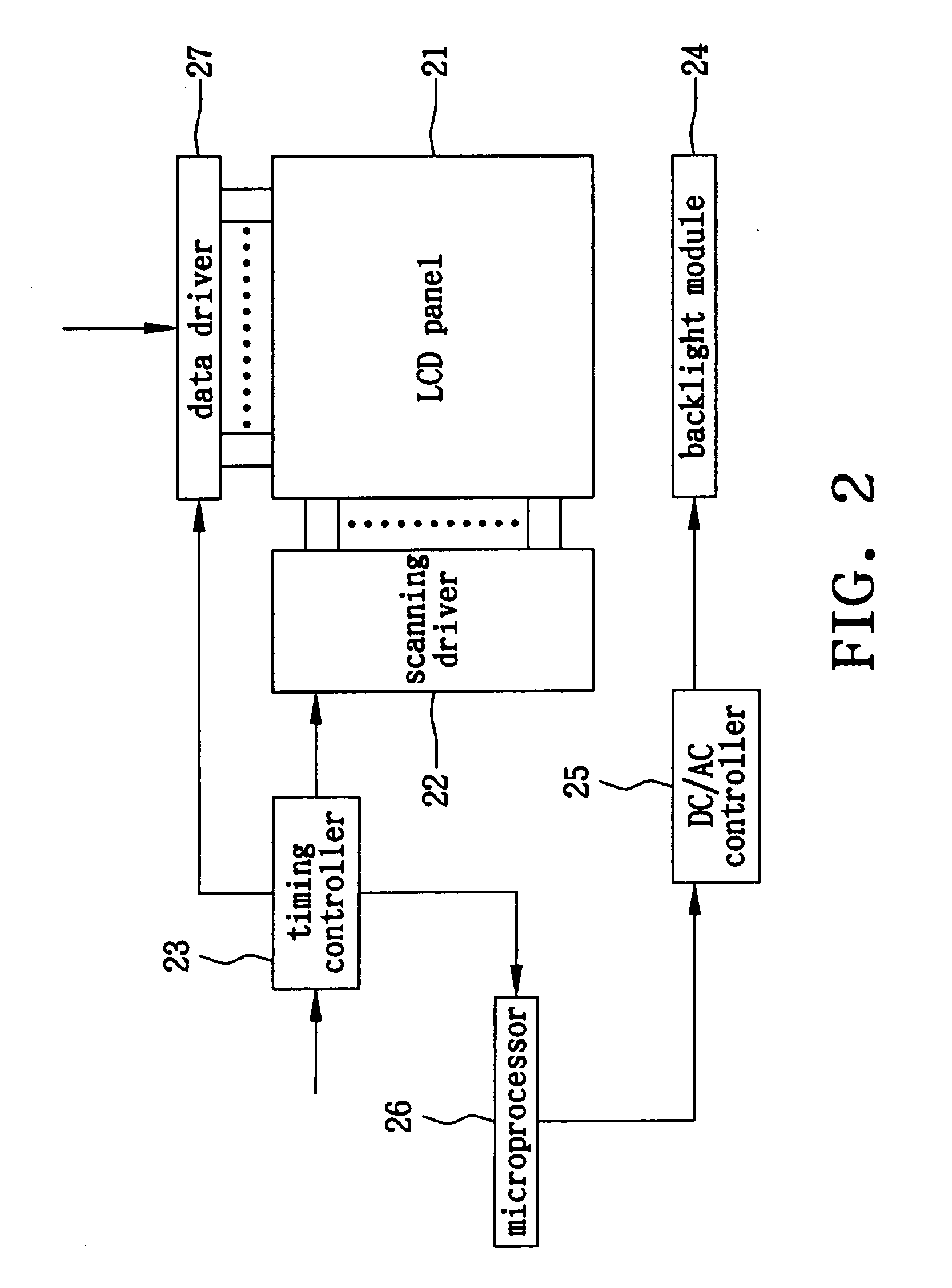
[0034] The present embodiment employs an LCD panel with 6-bits data signals to explain how to actually take advantage of Formula 2. The LCD panel comprises a plurality of pixels having R / G / B sub pixels. For example, the frame of a XGA LCD panel has demands for 768×1,024×3 gradation data.
[0035] R0-R5 respectively represents 6 gradation ranges, wherein if the data signal shows 000000, it represents the darkest gradation level L0, and if the data signal shows 111111, it represents the brightest gradation level L63. In the same way, G0-G6 and B0-B5 respectively represents the 6 gradation ranges of a green sub pixel and a blue sub pixel.
[0036] Px,y represents the pixel located at the intersection of the X data line and the Y scanning line. RPx,y(0) represents the gradation range R0 of the red sub pixels. In the same way, GPx,y(5) and BPx,y(5) respectively represent the brightest gradation ranges G5 for a green sub pixel and B5 for a blue sub pixel. WA, WB, WC, WD, W...
second embodiment
The Second Embodiment
[0044] Except one vertical scanning period can be designated as an modulating period for the luminous intensity of a backlight module, several vertical scanning periods can also be designated as an modulating period for that. WAN is the summation of all the values WA during consecutive N vertical scanning periods. In the same way, WBN and WCN are also derived.
[0045] After N (N=2−60) vertical scanning periods ending, the driving current of the backlight module can be determined by mathematical calculations expressed as follows:
[0046] (1) Let SN=2×WAN+WBN+0.5×WCN and S0=1000×N. When SN0 is satisfied, the driving current A0 is given as 2 micro amperes. That is, the luminous intensity of the backlight module is reduced to the lowest level to match up with a frame showing a darker imagine.
[0047] (2) Let SN=2×WAN+WBN+0.5×WCN and S1=0.05×1024×768×3. When S0N1 is satisfied, the driving current Al is given as 2.8 (=2+(6−2)×0.2) micro amperes, wherein the coefficient 0...
third embodiment
The Third Embodiment
[0052] Though the brightness distribution index is now expressed as Formula 5, in practical applications it is not limited by the expression of this formula, and is dependent on the characteristics or requirements of an LCD panel. The formula also can be expressed as a polynomial of multi-powers terms, trigonometric function terms or logarithmic function terms and other mathematical expressions. The embodiment employs multi-powers terms to replace terms with constant coefficients and ignores the effects of terms WD, WE and WF upon SN. The driving current of the backlight module can be determined by mathematical calculations expressed as follows:
[0053] (1) Let SN=WA2+WB+WC0.5 and S0=1000. When SN0 is satisfied, the driving current A0 is given as 2 micro amperes. That is, the luminous intensity of the backlight module is reduced to the lowest level to match up with a frame showing a darker imagine.
[0054] (2) Let SN=2×WA2+WB+0.5×WC0.5 and S1=0.05×1024×768×3. When ...
PUM
 Abstract
Description
Claims
Application Information
 - R&D
- Intellectual Property
- Life Sciences
- Materials
- Tech Scout
- Unparalleled Data Quality
- Higher Quality Content
- 60% Fewer Hallucinations
Browse by: Latest US Patents, China's latest patents, Technical Efficacy Thesaurus, Application Domain, Technology Topic, Popular Technical Reports.
© 2025 PatSnap. All rights reserved.Legal|Privacy policy|Modern Slavery Act Transparency Statement|Sitemap|About US| Contact US: help@patsnap.com


