
Opto-Mechanical Joint Assemblies

Inactive Publication Date: 2013-04-04
SUNCENT
View PDF10 Cites 6 Cited by
  • Summary
  • Abstract
  • Description
  • Claims
  • Application Information

AI Technical Summary

Benefits of technology

The invention is about creating a device that redirects light from a rotating part to a fixed point. This is achieved by using a concentrating element that can be rotated or tilted to track the light source. Reflective surfaces redirect the light to the fixed point, regardless of the orientation of the concentrating element. A light receiving port can be positioned at the fixed point to collect the incident light. The invention helps to reduce hot spots and can be used in various applications such as optical communication systems.

Problems solved by technology

Previous work on building daylight illumination has not been successful for a number of reasons.
Passive daylighting efforts including skylights, vertical light pipes, and other methods of directing non-concentrated or untracked sunlight fail to meet commercial illumination standards over a practical area or during a reasonable percentage of the year and do not provide significant power savings.
The collected light would not, therefore, be expected to travel efficiently any distance once inside the building envelope.
Control of light distribution is also problematic due to the wide range of angles of light entering the building.
Previous active daylighting, herein referred to as “sunlighting”, efforts also have significant limitations that affect system cost or life cycle.
Designs that include an optical fiber mounted such that it moves with the tracking optics are limited by the resistance caused by the bulky array of moving fiber.
Accurate tracking in those cases is costly to provide.
The light collecting element and optical fibers receiving the collected light must also move with the apparatus, which creates problems in keeping the light collecting element aligned to collect sunlight efficiently, and leads to lost light as the optical fiber flexes.
Generally, designs that utilize long optical fibers from the collector to the lighting fixture are further limited by the properties of the optical fiber over long distances, which distances cause significant light losses due to bulk absorption and noticeable color spectrum shifts.
Although there are several patents and patent publications pertaining to the concept of concentrating sunlight, or suggesting moving to track the sun, no solutions are offered for a whole apparatus system to make sunlight illumination work in a real context.
The related art discloses solutions that have cost and performance issues related to relying on optical fiber to transport light over long distances, requiring high tracking accuracy required to minimize fiber diameter, and having reduced tracking mechanism accuracy limitations when needing to flex fiber.

Method used


Image

  • Opto-Mechanical Joint Assemblies
  • Opto-Mechanical Joint Assemblies
  • Opto-Mechanical Joint Assemblies

Examples


Embodiment Construction

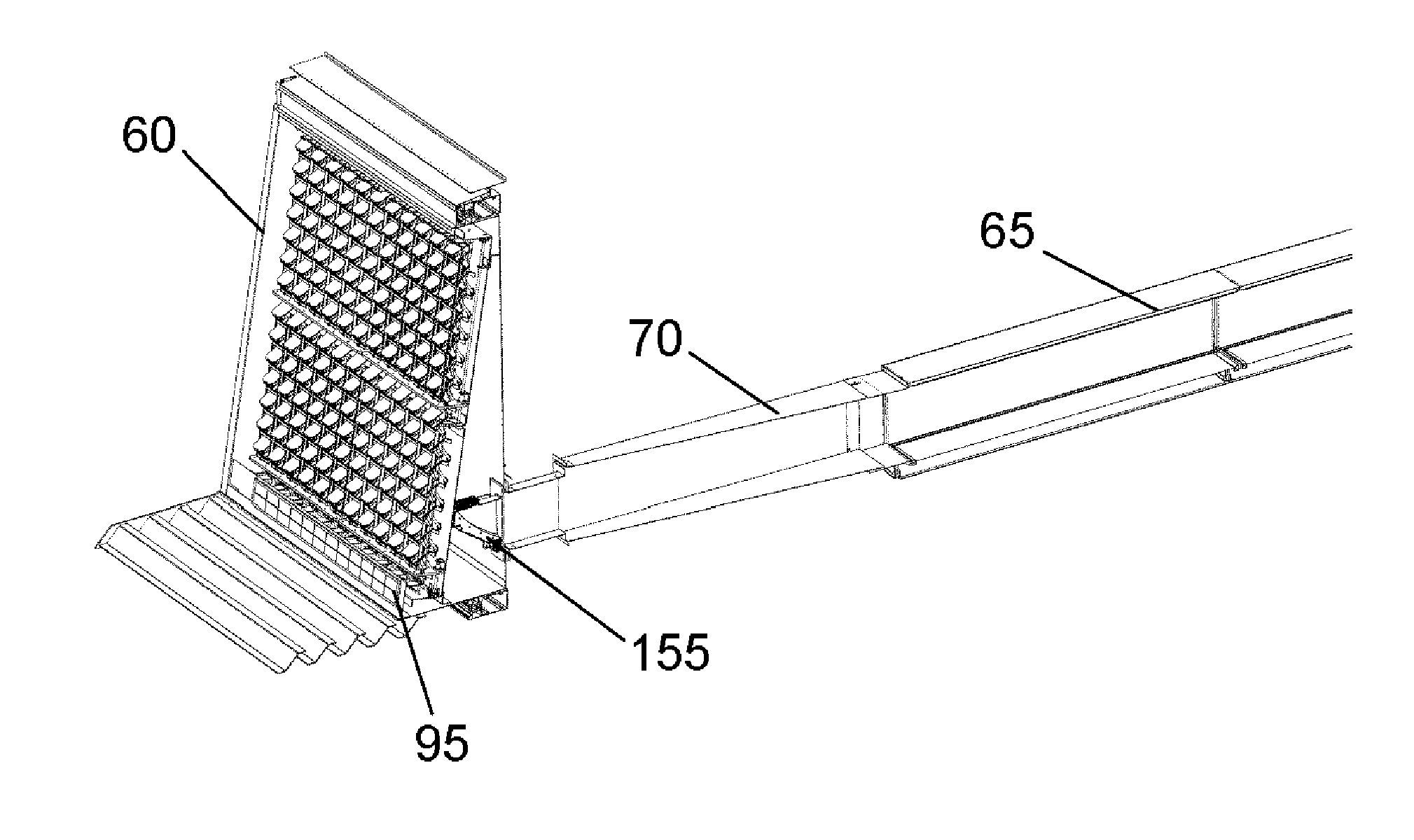
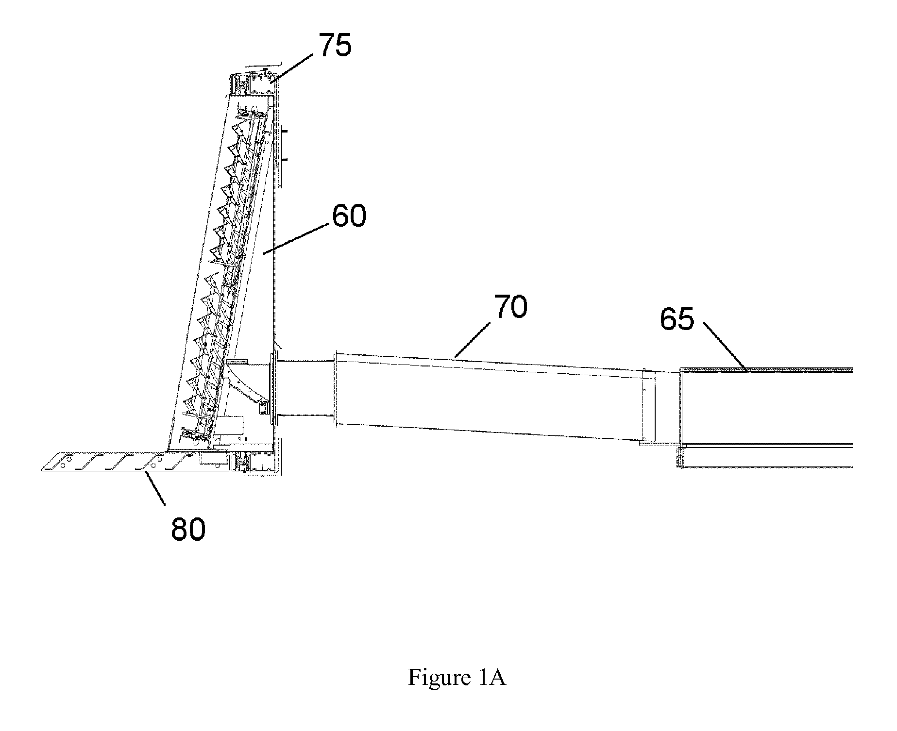
[0032]One should appreciate that the disclosed techniques provide many advantageous technical effects including routing natural light from an exterior portion of a structure to an interior portion of the structure. More specifically, the disclosed subject matter provides the technical affect of routing light along an optical path through an opto-mechanical joint to a fixed point regardless of the incident orientation of the light.

[0033]The following discussion provides many example embodiments of the inventive subject matter. Although each embodiment represents a single combination of inventive elements, the inventive subject matter is considered to include all possible combinations of the disclosed elements. Thus if one embodiment comprises elements A, B, and C, and a second embodiment comprises elements B and D, then the inventive subject matter is also considered to include other remaining combinations of A, B, C, or D, even if not explicitly disclosed.

[0034]As used herein, and u...


PUM


Abstract

A light collecting and disseminating apparatus is provided for use in harvesting sunlight from the exterior of a man-made structure, and providing light to the inside of the structure, via an opto-mechanical joint where sunlight would not normally be available. The internal arrangement of the collector allows for improved optical accuracy and performance over prior efforts. The apparatus is also characterized as possessing a low profile so as not to alter the appearance of buildings furnished with the invention. Further, light can be collected from any orientation and redirected through the opto-mechanical joint to a stationary light receiving port independent of the orientation of the collectors.

Description

[0001]This application claims the benefit of priority to U.S. provisional application having Ser. No. 61 / 541,305 filed on Sep. 30, 2011, which is incorporated by reference herein in its entirety.FIELD OF THE INVENTION[0002]The field of the invention is light redirection technologies. Background[0003]Core daylight illumination apparatus systems for buildings are intended to collect, concentrate and direct sunlight from the exterior of the building to internal workspaces for the purposes of replacing a portion of the normally required electrically powered lighting and of improving lighting quality within those workspaces. Widespread use of such systems in commercial workspaces could significantly reduce energy consumption and greenhouse gas emissions. To foster widespread usage, the building core daylight illumination systems must be cost effective, robust, and compatible with common commercial building design and construction practices.[0004]Previous work on building daylight illumin...

Claims


Application Information

Patent Timeline
IPC IPC(8): G02B6/26G02B6/32
CPCF21S11/00
Inventor SCOTT, JON DAVID EDWARDUPWARD, ALLEN JAMESFRIEDEL, PETER GEORGEMOSHER, MARK RICHARD
Owner SUNCENT
Learn More