Mapping catheter with spiral electrode assembly

Inactive Publication Date: 2013-04-04
BIOSENSE WEBSTER (ISRAEL) LTD
View PDF4 Cites 28 Cited by
  • Summary
  • Abstract
  • Description
  • Claims
  • Application Information

AI Technical Summary

Benefits of technology

[0014]The present invention is directed to a mapping catheter having a mapping electrode assembly that resembles a ribbon and is shaped in spiral form. The mapping electrode assembly has a support structure with shape memory and carries an array of electrodes fixed to an outer surface of the ribbon. When the mapping electrode assembly is expanded, multiple electrodes on the ribbon advantageously come into contact with tissue wall of a heart chamb

Problems solved by technology

Cardiac arrhythmias, the most common of which is ventricular tachycardia (VT), are a leading cause of death.
One drawback with mapping a cardiac chamber using a catheter containing only a single

Method used


Image

  • Mapping catheter with spiral electrode assembly
  • Mapping catheter with spiral electrode assembly
  • Mapping catheter with spiral electrode assembly

Examples


Embodiment Construction

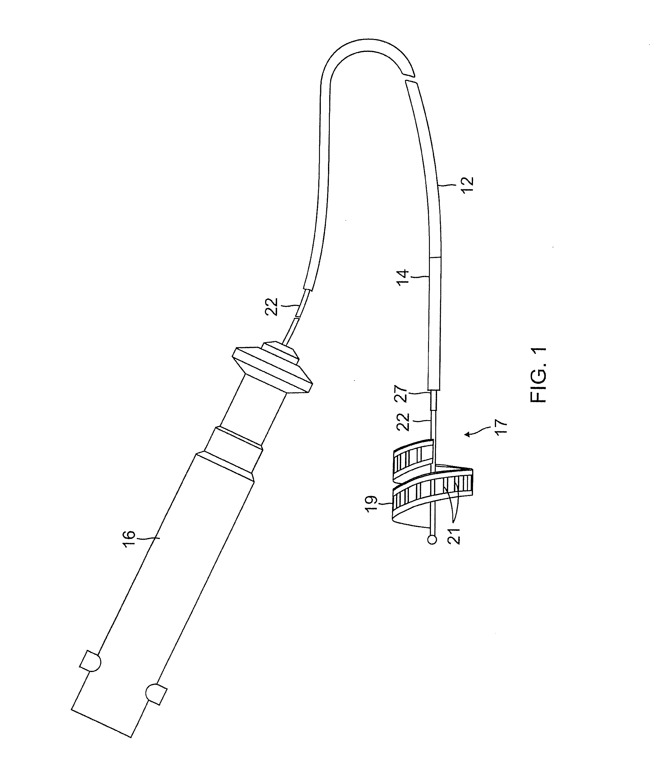
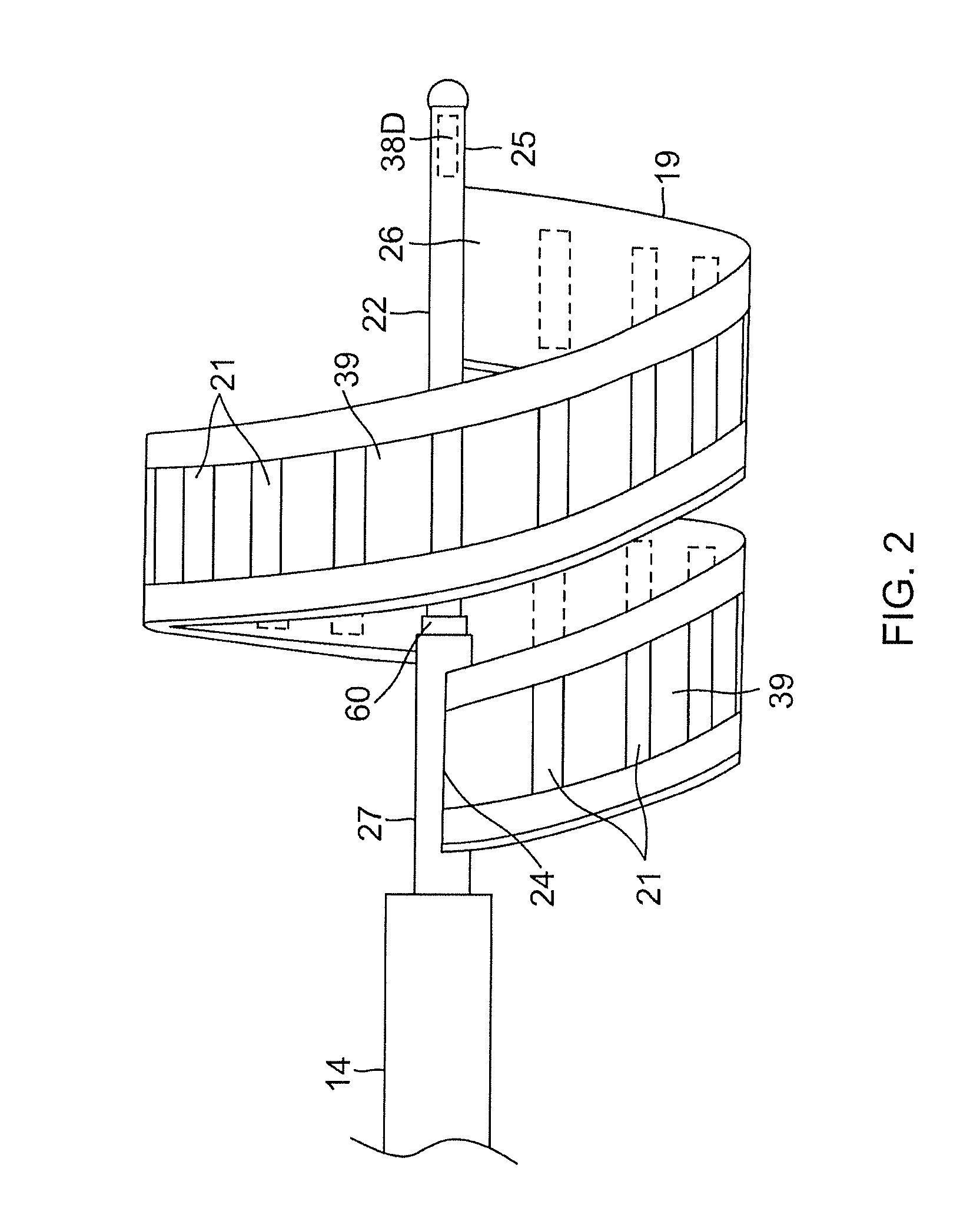
[0042]As illustrated in FIGS. 1-4 the present invention includes a steerable catheter 10 with a distal tip section 17 that includes a distal mapping electrode assembly 19 carrying a plurality of electrodes 21 for multiple simultaneous contacts with wall tissue of a chamber, including a heart chamber 20, such as an atrium or ventricle. The assembly includes a flexible planar member or band resembling a “ribbon”28 that is supported on an expander 22 in a generally spiral configuration. Advantageously, the expander can be advanced and retracted relative to the catheter to vary the spiral configuration, including radially expanding (FIG. 2) and contracting the ribbon 28 (FIG. 3). The ribbon has a proximal end 24 and a distal end 26. The proximal end 24 is fixed to an outer sleeve 27 through which the expander 22 can move longitudinally, and the distal end 26 is fixed to a distal end 25 of the expander 22. As such, the spiral configuration of the ribbon 28 is varied as the expander 22 is...


PUM


Abstract

A mapping catheter adapted for use in a heart chamber, has a distal mapping assembly with a spiral ribbon that is radially expandable and contractable by means of an expander so that electrodes on the ribbon can contact heart wall at a plurality of locations simultaneously. The expander extends the length of the catheter between a control handle and a distal end of the spiral ribbon. The expander can be controlled directly at its proximal end by a user or the expander can be responsive to a puller wire controlled by a user interface on the control handle.

Description

FIELD OF INVENTION[0001]The invention is directed to catheters for rapidly generating an electrical map of a chamber of a heart utilizing an assembly of contact electrodes for obtaining information indicative of chamber electrical activity, and optionally, of chamber geometry.BACKGROUND[0002]Cardiac arrhythmias, the most common of which is ventricular tachycardia (VT), are a leading cause of death. In a majority of patients, VT originates from a 1 mm to 2 mm lesion located close to the inner surface of the heart chamber. One of the treatments for VT comprises mapping the electrical pathways of the heart to locate the lesion followed by ablation of the active site.[0003]Commonly assigned U.S. Pat. No. 5,546,951; U.S. patent application Ser. No. 08 / 793,371; and PCT application WO 96 / 05768, which are incorporated herein in their entirety by reference, disclose methods for sensing an electrical property of heart tissue, for example, local activation time, as a function of the precise lo...

Claims


Application Information

Patent Timeline
IPC IPC(8): A61B5/0408
CPCA61B5/0422A61B5/287
Inventor GRUNEWALD, DEBBY
Owner BIOSENSE WEBSTER (ISRAEL) LTD
Why Eureka
Try Eureka