Supercharge Your Innovation With Domain-Expert AI Agents!

Optical pickup

a technology of optical pickups and pickups, applied in the field of optical pickups, can solve the problems of difficulty in visually confirming defects that the gel cannot reach, difficulty in setting the servo gain, and difficulty in achieving the effect of reducing the cost and variation of performance, reducing the variation of applying conditions, and simplifying the assembling

Inactive Publication Date: 2013-04-04
HITACHI MEDIA ELECTORONICS CO LTD
View PDF8 Cites 2 Cited by
  • Summary
  • Abstract
  • Description
  • Claims
  • Application Information

AI Technical Summary

Benefits of technology

The present invention provides an optical pickup that reduces costs and performance variations by simplifying assembly and reducing variations in gel application.

Problems solved by technology

According to the technology in Japanese Unexamined Patent Application Publication No. 2003-346367, it is difficult to visually confirm a defect that the gel does not reach the lowest of the support members disposed in the focusing direction because the inside of the gel holding part is visible only from the optical disc side in the focusing direction.
In this case, the amplitude of the translational mode of a moving part, which is decided by the rigidity of the support members and the mass of the moving part, may not be sufficiently damped and setting of the servo gain, which is for making the position of the object lens follow axial and radial run-out of the optical disc, may become difficult.
In this case, it possibly takes time for assembling because a gel applying step and an irradiation with ultraviolet light step are required.

Method used


Image

  • Optical pickup
  • Optical pickup
  • Optical pickup

Examples


first embodiment

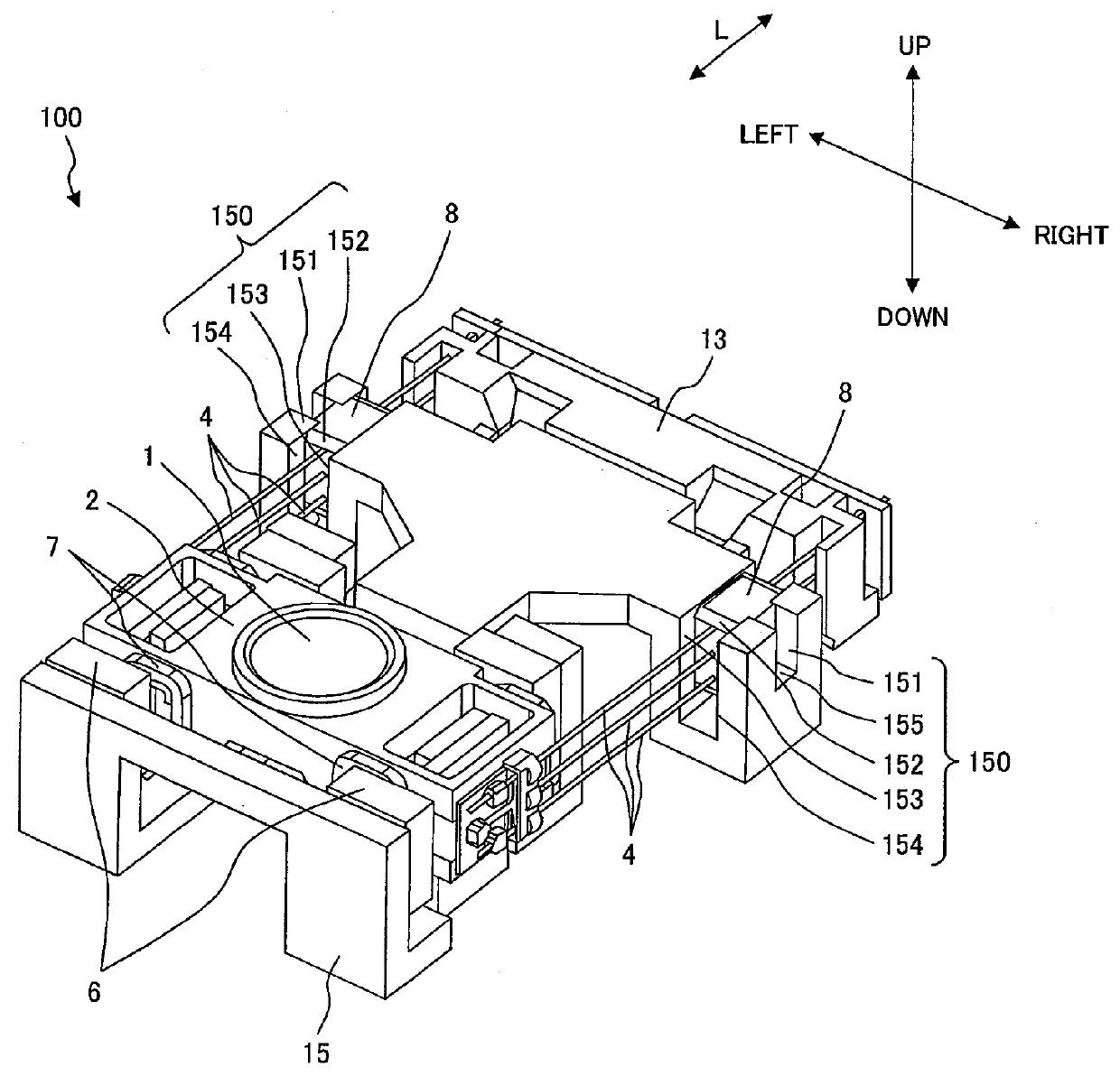
[0022]In the present embodiment, an optical pickup will be described which drives an object lens in the focusing direction and the tracking direction and aligns the position of a focal point of the object lens to a target track on a recording surface of an optical disc in order to read information recorded on the recording surface of the optical disc or to write information on the recording surface of the optical disc.

[0023]First, the optical pickup will be described referring to FIG. 6.

[0024]FIG. 6 is a schematic view of an optical pickup in accordance with the first embodiment of the present invention.

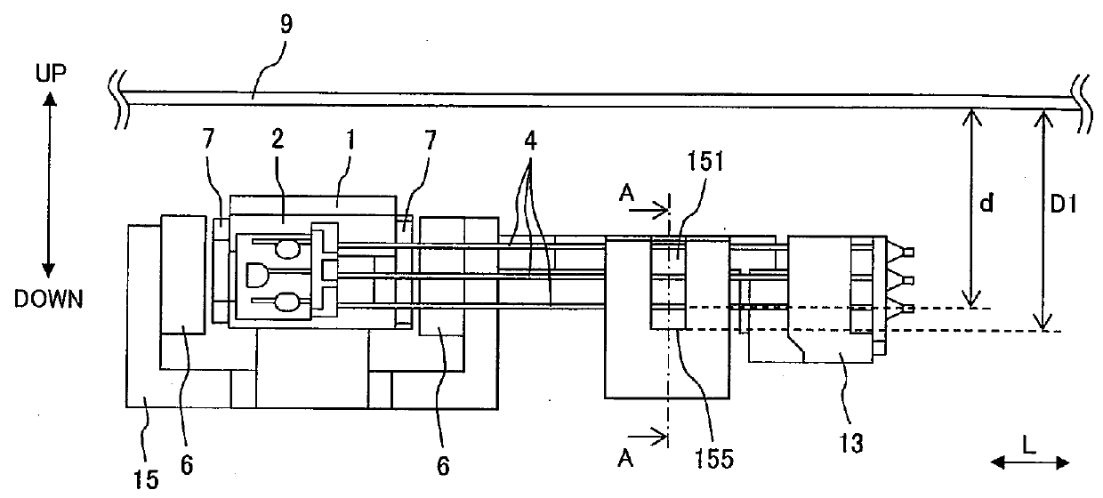
[0025]In FIG. 6, directions are defined such that a direction in which an object lens 1 moves toward an optical disc (not illustrated) is up, and a direction in which the object lens 1 moves away from the optical disc is down. This up and down direction (vertical direction) , which is indicated in FIG. 6, is the focusing direction. Right and left direction indicated in FIG. 6 is the ...

second embodiment

[0044]In the present embodiment, an optical pickup will be described in which the gel holding parts are integrated in the fixing part instead of in the yoke.

[0045]FIG. 4 is a schematic view of an object lens actuator 200 of an optical pickup in accordance with a second embodiment of the present invention. Description will be omitted for elements of the object lens actuator 200 in FIG. 4 having the same reference numerals and same functions as those in FIG. 1.

[0046]In FIG. 4, the object lens actuator 200 includes a fixing part 23 in which both right and left sides extend toward the moving part along the longitudinal direction L of the support members 4, and gel holding parts 230 are integrated in the fixing part 23 at the extending parts.

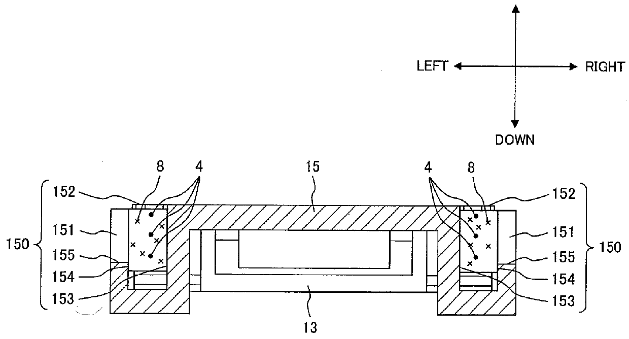
[0047]Each of the gel holding parts 230 includes an opening 232 in a face on the optical disc side in the focusing direction, walls 233, 234 on both sides of the support members 4 in the tracking direction, the support members 4 being disposed on bot...


PUM

PropertyMeasurementUnit
distanceaaaaaaaaaa
rigidityaaaaaaaaaa
timeaaaaaaaaaa

Abstract

An optical pickup includes an object lens; a moving part including the object lens and coils; rod-shaped support members disposed in a focusing direction, one end of each of the support members being attached to side surfaces of the moving part in a tracking direction; a fixing part for fixing the other end of each of the support members; a yoke including magnets; and gel holding parts, each of the gel holding parts including walls on both sides of the support members in the tracking direction, and the support members being disposed on both sides of the moving part in the tracking direction. Each of the gel holding parts includes an opening at one end on an optical disc side in the focusing direction and includes a cutout in the wall farther from the object lens in the tracking direction, the cutout extending from an edge of the opening.

Description

CLAIM OF PRIORITY[0001]The present application claims priority from Japanese Patent Application JP 2011-217587 filed on Sep. 30, 2011, the content of which is hereby incorporated by reference into this application.FIELD OF THE INVENTION[0002]The present invention relates to an optical pickup for driving an object lens in the focusing direction and the tracking direction and aligning the position of a focal point of the object lens to a target track on a recording surface of an optical disc in order to read information recorded on the recording surface of the optical disc or to write information on the recording surface of the optical disc.BACKGROUND OF THE INVENTION[0003]One of the conventional technologies of the field of the invention is disclosed in Japanese Unexamined Patent Application Publication No. 2003-346367. This document discloses an object lens actuator including gel holding parts in which gel for a damper is poured into gaps between a fixing part which support members ...

Claims


Application Information

Patent Timeline
Patent Type & Authority Applications(United States)
IPC IPC(8): G11B7/09
CPCG11B7/0933G11B7/0932
Inventor OCHI, MANABUKIMURA, KATSUHIKOSAITO, HIDENAO
Owner HITACHI MEDIA ELECTORONICS CO LTD
Features
  • R&D
  • Intellectual Property
  • Life Sciences
  • Materials
  • Tech Scout
  • Unparalleled Data Quality
  • Higher Quality Content
  • 60% Fewer Hallucinations
Learn More