
Device and method for changing elongated objects
a technology of elongated objects and devices, applied in the field of devices and methods for changing elongated objects, can solve the problems of affecting the effect of energy consumption, affecting the effect of advertising, and limiting the space of known devices, and achieve the effect of energy saving
- Summary
- Abstract
- Description
- Claims
- Application Information
AI Technical Summary
Benefits of technology
Problems solved by technology
Method used
Image

Examples
Embodiment Construction
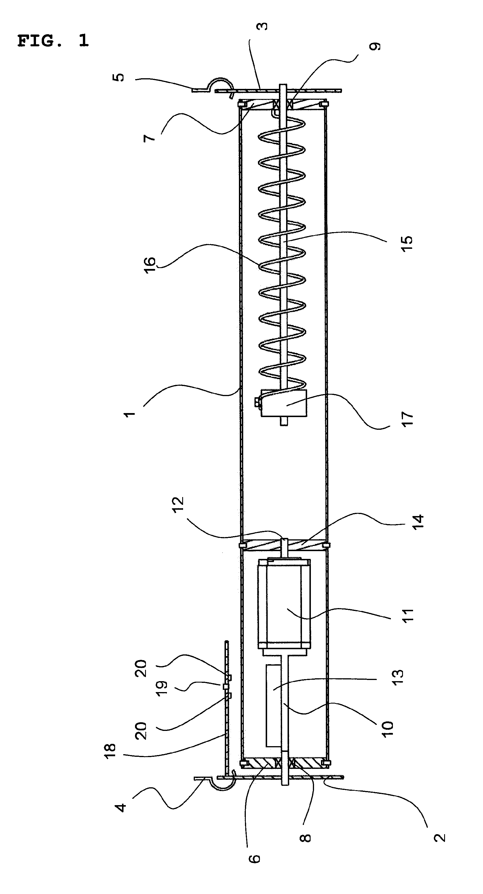
[0020]The embodiment of the present invention will now be described. First of all the parts comprising the device will be described as depicted in the partly cross sectional view of FIG. 1.
[0021]The device comprises a drum 1 with rotational freedom between two end holding means 2, 3, preferably in the shape of discs. At each end the drum 1 is fitted with end covers 6 and 7 respectively. From a first end holding means 2 a motor holding bar 10 protrudes through the end cover 6. A motor 11 for rotating the drum 1 of the device is provided inside the drum 1 and is held in place by the motor holding bar 10. A controller unit 13 for controlling the speed and direction of the motor 11 as well as other aspects of the operation of the device is mounted on the motor holding bar 10. The motor 11 exerts its torque to the drum 1 via a driving disc 14. An output shaft 12 from the motor 11 is connected to the driving disc 14 in such a way that when the shaft 12 rotates the driving disc 14 also rot...
PUM
| Property | Measurement | Unit |
|---|---|---|
| flexible | aaaaa | aaaaa |
| magnetic force | aaaaa | aaaaa |
| distances | aaaaa | aaaaa |
Abstract
Description
Claims
Application Information