Manufacturing device for permanent magnet disposed in rotating electrical machine and manufacturing method of the same

a technology of manufacturing device and permanent magnet, which is applied in the direction of auxillary welding device, magnetic body, paper/cardboard container, etc., and can solve the problems of limited motor performan

Active Publication Date: 2013-04-11
NISSAN MOTOR CO LTD
View PDF1 Cites 8 Cited by
  • Summary
  • Abstract
  • Description
  • Claims
  • Application Information

AI Technical Summary

Benefits of technology

[0005]Therefore, the present invention has an object to provide a manufacturing device for a permanent magnet disposed in a rotating electrical machine suitable for ensuring a magnet dimension and a manufacturing method of the same.

Problems solved by technology

As a result, motor performances are also restricted.

Method used


Image

  • Manufacturing device for permanent magnet disposed in rotating electrical machine and manufacturing method of the same
  • Manufacturing device for permanent magnet disposed in rotating electrical machine and manufacturing method of the same
  • Manufacturing device for permanent magnet disposed in rotating electrical machine and manufacturing method of the same

Examples


first embodiment

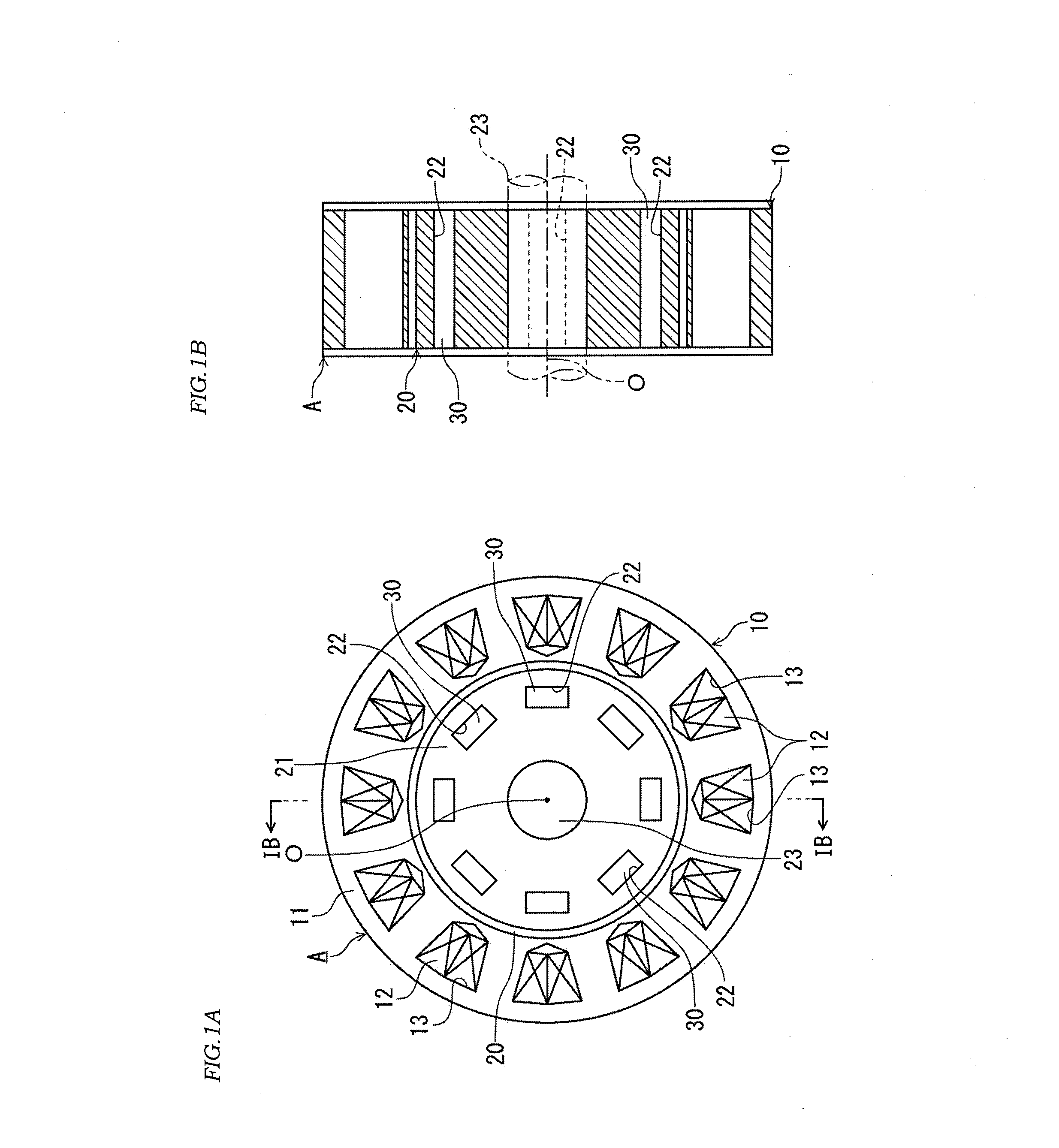
[0025]FIG. 1A is a front view illustrating an outline configuration of a rotating electrical machine to which a permanent magnet according to an embodiment of the present invention is applied. FIG. 1B is a sectional view along IB-IB line in FIG. 1A.

[0026]A permanent-magnet embedded rotating electrical machine A (hereinafter referred to simply as a “rotating electrical machine”) is formed of an annular stator 10 constituting a part of a casing, not shown, and a columnar rotor 20 arranged coaxially with this stator 10.

[0027]The stator 10 includes a stator core 11 and a plurality of coils 12. In the stator core 11, slots 13 are formed at equiangular intervals on the same circumference having a shaft center O at the center. The plurality of coils 12 are accommodated in the slots 13 formed in the stator core 11.

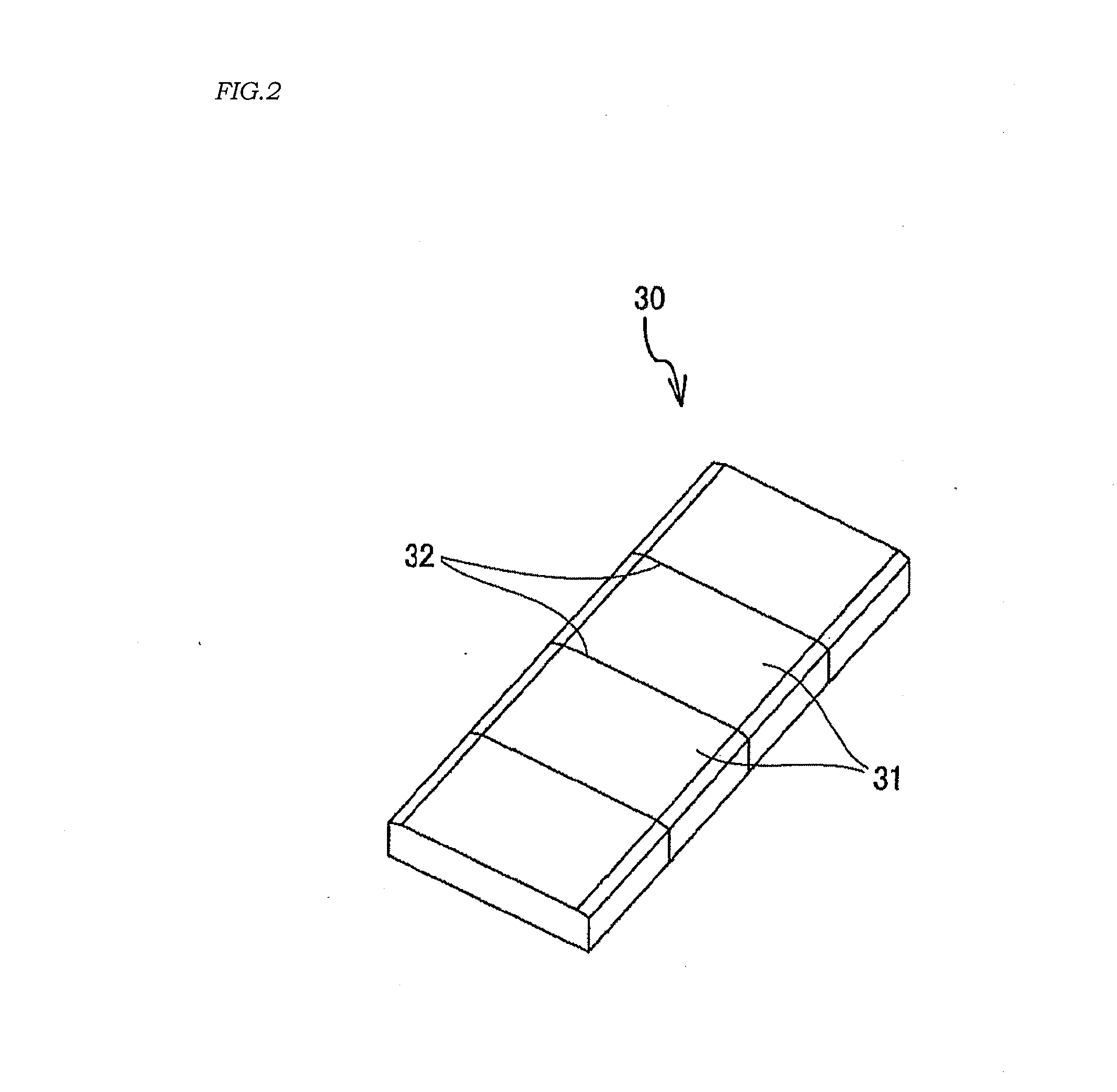
[0028]The rotor 20 includes a rotor core 21, a rotating shaft 23 rotating integrally with the rotor core 21, and a plurality of permanent magnets 30. In the rotor core 21, slots 2...

second embodiment

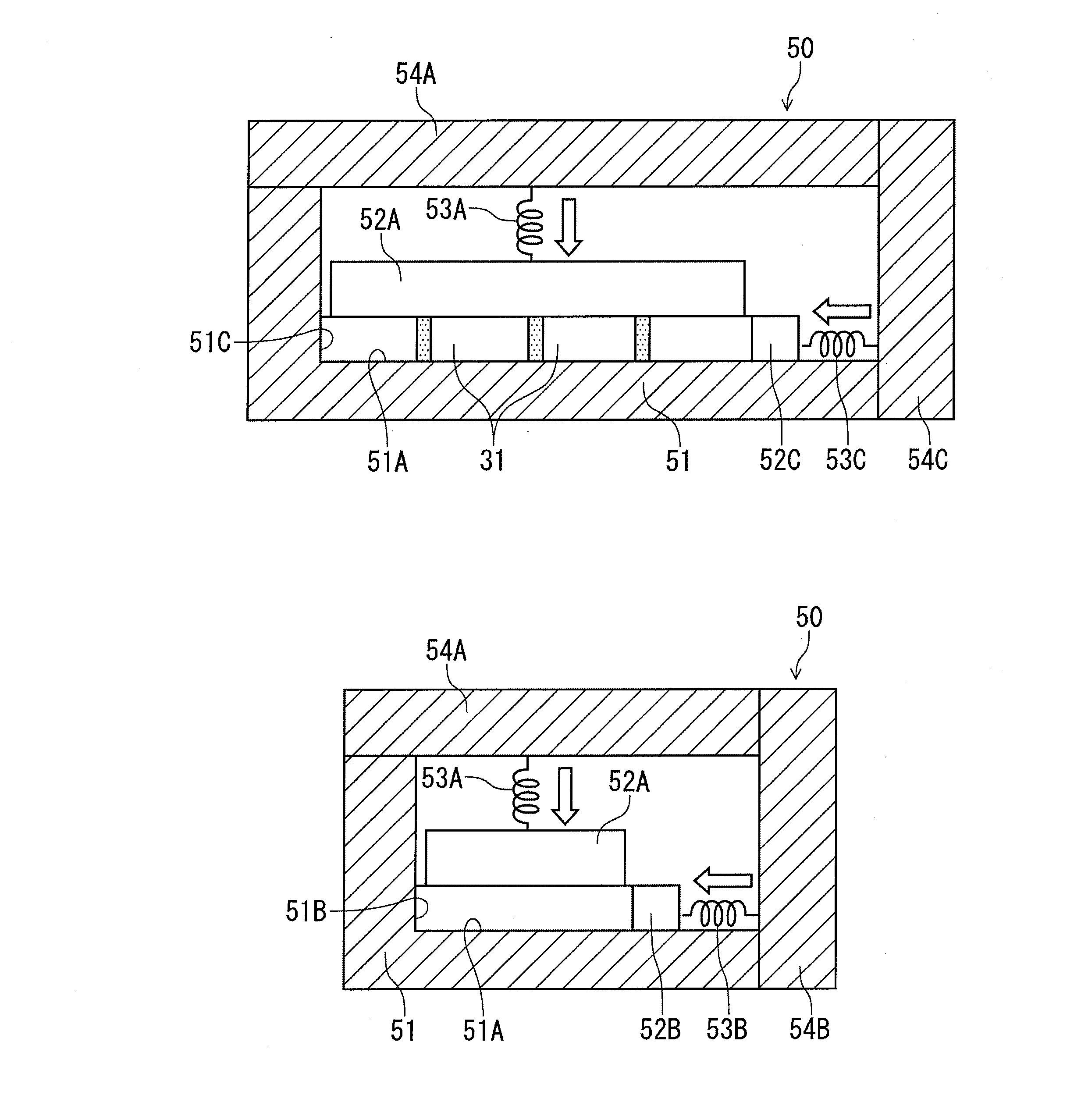
[0072]FIGS. 9 to 11 illustrate a second embodiment of a manufacturing device for a permanent magnet to be embedded in a rotor core of a rotating electrical machine to which the present invention is applied and a manufacturing method of the same. That is, FIG. 9 is a side view of an integrating jig, FIG. 10 is an explanatory diagram of a spring device used in the integrating jig, and FIG. 11 is a side view of an operation state of the integrating jig. In this embodiment, a configuration in which the pressing force to be imparted to at least either one of the thickness-direction movable member 52A and the width-direction movable member 52B is changed in accordance with an atmospheric temperature is added to the first embodiment. The same devices as those in the first embodiment are given the same reference numerals and the description will be omitted or simplified.

[0073]In the integrating jig 50 in this embodiment, the pressing force to be imparted to at least one of the thickness-dir...


PUM

PropertyMeasurementUnit
heat resistanceaaaaaaaaaa
temperatureaaaaaaaaaa

Abstract

This invention is a manufacturing device for a permanent magnet disposed in a rotating electrical machine, in which a plurality of magnet pieces, each formed by being fractured and split along a notch groove, are aligned and joined to each other with an adhesive interposed between fractured surfaces. First pressing means for aligning the plurality of fractured and split magnet pieces with the fractured surfaces opposed to each other in a thickness direction by pressing from the thickness direction of the permanent magnet, second pressing means for aligning the plurality of magnet pieces in a width direction by pressing from a width direction of the permanent magnet are provided. Moreover, third pressing means for joining the opposing fractured surfaces of the magnet piece with the interposed adhesive by pressing the plurality of magnet pieces from a longitudinal direction of the permanent magnet.

Description

TECHNICAL FIELD[0001]The present invention relates to a manufacturing device for a permanent magnet disposed in a rotating electrical machine and a manufacturing method of the same.BACKGROUND ART[0002]A technology for using a permanent magnet formed by cleaving and splitting so as to reduce a surface area in a rotor core of a rotating electrical machine is known. By forming the permanent magnet as above, an eddy current generated by fluctuation in a magnetic field is reduced. Then, heat generation of the permanent magnet caused by the eddy current is suppressed. As a result, irreversible thermal demagnetization can be prevented.[0003]A method of cleaving a permanent magnet is described in JP2009-142081A. In this JP2009-142081A, the inside of a container having an inside hollow dimension and an inside hollow shape equal to a dimension and a shape of a rotor slot is used. First, a resin is filled in this container. Subsequently, a permanent magnet provided in advance with a notch whic...

Claims


Application Information

Patent Timeline
Patent Type & Authority Applications(United States)
IPC IPC(8): H01F41/02
CPCH01F7/0205H01F41/0253H02K15/03Y10T29/49075Y10T29/49012Y10T29/49076Y10T156/10Y10T29/49009H01F7/0221H01F41/02
Inventor TAKAICHI, KAZUHIROISHIGURO, KUNITOMO
Owner NISSAN MOTOR CO LTD
Why Eureka
Try Eureka