Particle control in laser processing systems

a laser processing system and particle control technology, applied in manufacturing tools, lighting and heating apparatus, furnaces, etc., can solve the problems of undetectable redeposit and ablation of substrate parts, and achieve the effect of reducing contamination and reducing contamination

Active Publication Date: 2013-04-11
APPLIED MATERIALS INC
View PDF33 Cites 12 Cited by
  • Summary
  • Abstract
  • Description
  • Claims
  • Application Information

AI Technical Summary

Benefits of technology

This patent describes new ways to use a laser to process materials by adding a protective layer called a shield. The shelter helps keep debris away from the material being heated up. It also contains gases like nitrogen or ozone to help clean any harmful chemicals off. These improvements make it easier to get high quality results when using the laser without causing damage to the material.

Problems solved by technology

This patent describes a problem with traditional methods of thermally treating materials like silicon wafers. During this process, certain gases and particles are created that have negative effects on the quality of the finished product if they aren't properly removed. There is also a risk of contamination due to these harmful substances being released back onto the wafer after treatment. Therefore, the technical problem addressed by this patent is finding a way to effectively remove these unwanted byproducts without compromising the efficiency and effectiveness of the overall thermal annealing process.

Method used


Image

  • Particle control in laser processing systems
  • Particle control in laser processing systems
  • Particle control in laser processing systems

Examples


Embodiment Construction

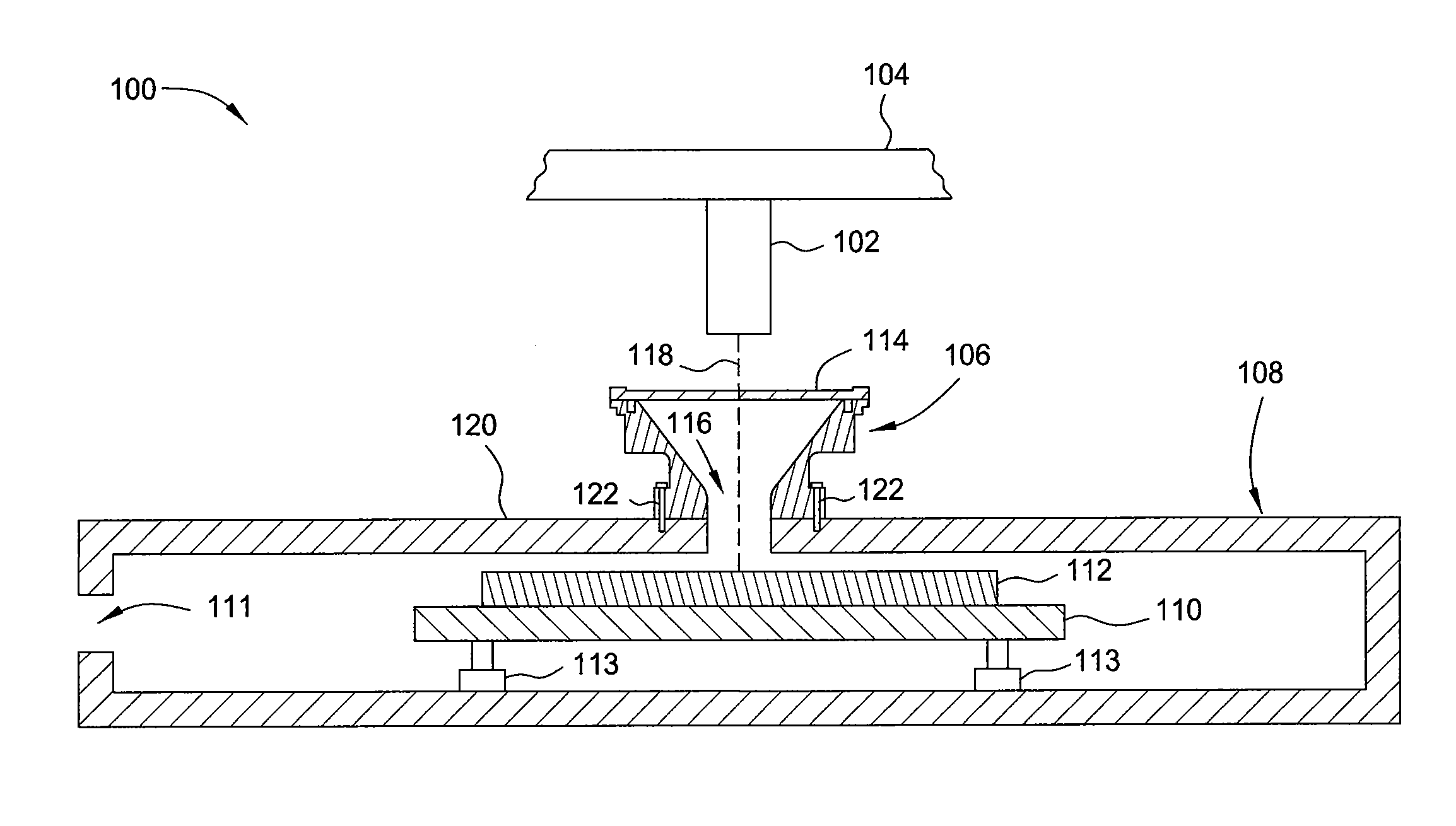
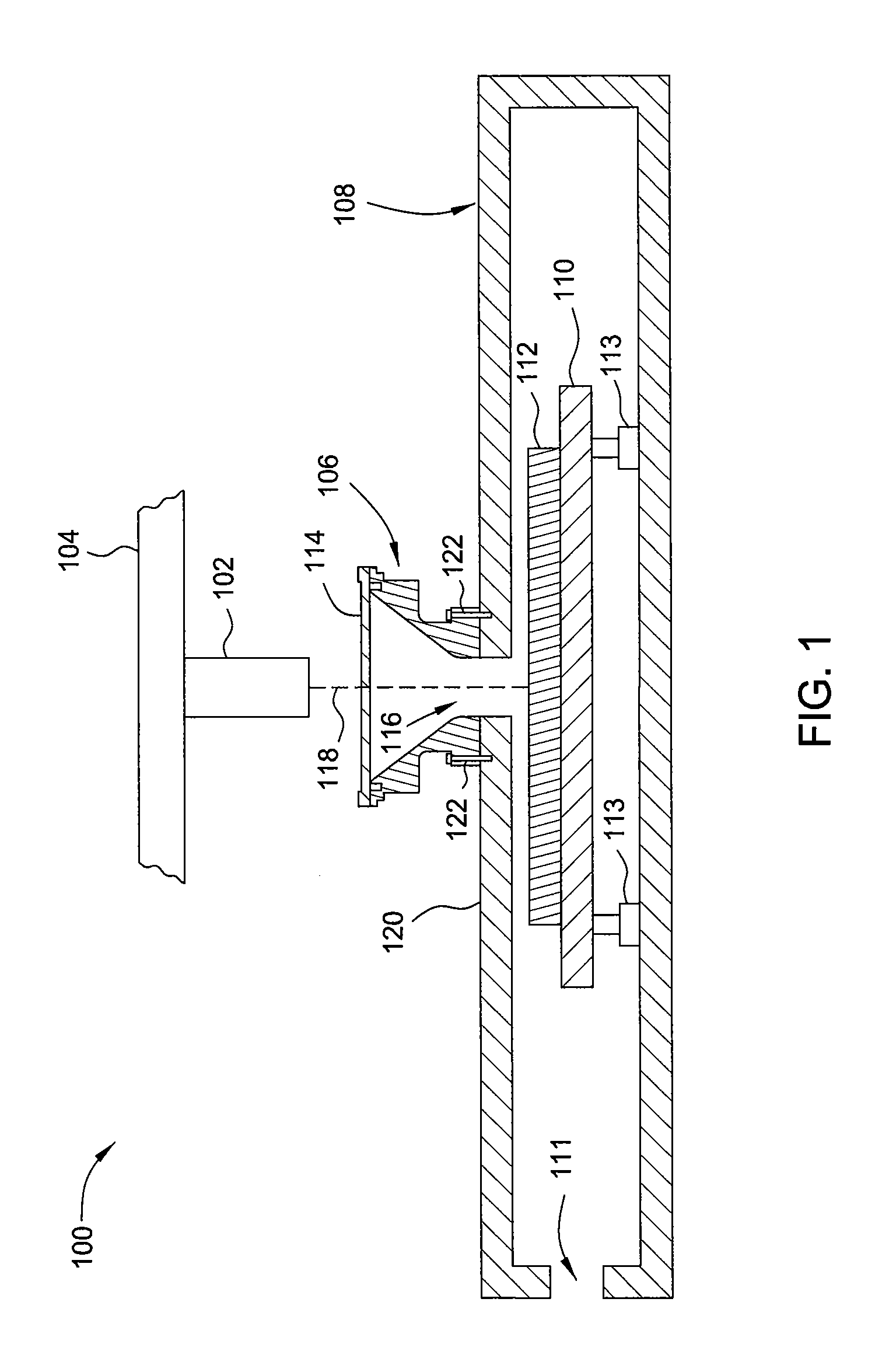
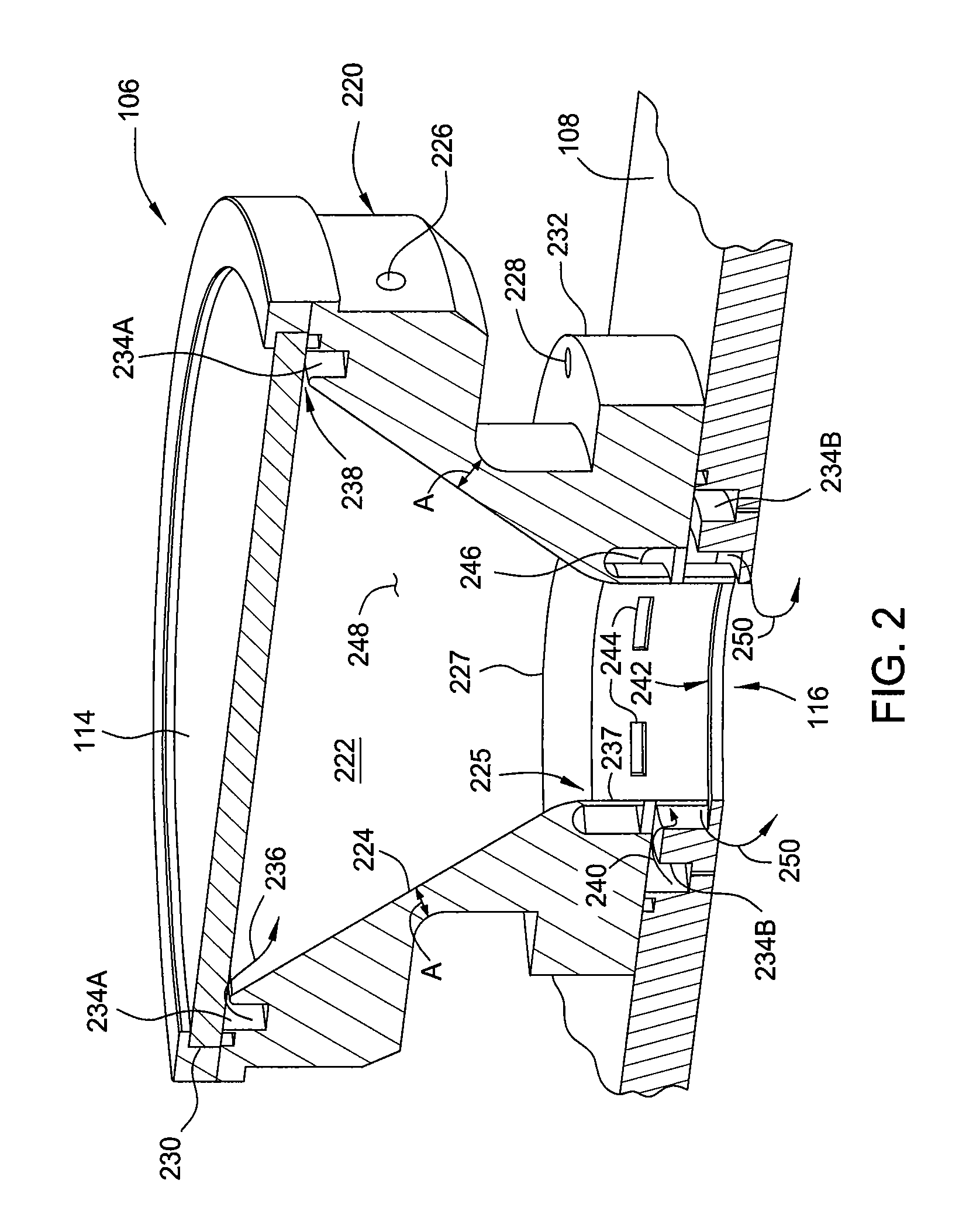
[0015]The present invention generally relates to a laser processing systems for thermally processing substrates. The laser processing systems include a shield disposed between an energy source of the laser processing system and a substrate which is to be thermally processed. The shield includes an optically transparent window disposed adjacent to a cavity within the shield. The optically transparent window allows annealing energy to pass therethrough and to illuminate the substrate. The shield also includes one or more gas inlets and one or more gas outlets for introducing and removing a purge gas from the cavity within the shield. The purge gas is utilized to remove volatized or ablated components during thermal processing, and to provide a gas of predetermined composition, such as oxygen-free, to the thermally processed area.

[0016]FIG. 1 is a sectional view of a laser processing system 100 according to one embodiment of the invention. The laser processing system 100 includes an en...


PUM

PropertyMeasurementUnit
Wavelengthaaaaaaaaaa

Abstract

The present invention generally relates to a laser processing systems for thermally processing substrates. The laser processing systems include a shield disposed between an energy source of the laser processing system and a substrate which is to be thermally processed. The shield includes an optically transparent window disposed adjacent to a cavity within the shield. The optically transparent window allows annealing energy to pass therethrough and to illuminate the substrate. The shield also includes one or more gas inlets and one or more gas outlets for introducing and removing a purge gas from the cavity within the shield. The purge gas is utilized to remove volatized or ablated components during thermal processing, and to provide a gas of predetermined composition, such as oxygen-free, to the thermally processed area.

Description


Claims


Application Information

Patent Timeline
Owner APPLIED MATERIALS INC
Why Eureka
Try Eureka