Motor having more magnets on effective area of the rotor thereof

a technology of effective area and rotor, which is applied in the direction of dynamo-electric machines, magnetic circuit rotating parts, magnetic circuit shape/form/construction, etc., can solve the problems of easy introduction of running and inability to fully enhance the efficiency of the motor

Inactive Publication Date: 2013-04-11
RECHI PRECISION
View PDF5 Cites 5 Cited by
  • Summary
  • Abstract
  • Description
  • Claims
  • Application Information

AI Technical Summary

Benefits of technology

[0010]To achieve the foregoing objective, the present invention consists of a stator, a rotor and a rotation shaft, the rotor forms a plurality number of rotor poles, each rotor pole has a magnet, a concave arc is on the outer side of each magnet, and forms the first, the second and the third surfaces near inside of each magnet, the concave arc connects to the first and the third surfaces with connecting plans respectively, each connecting plan nears the periphery surface of that rotor, the angles formed by the first surface, the third surface with the second surface are θ1, and θ3 respectively, when the number of rotor magnet poles is P that satisfies “90+ (180 / P)” degree condition, the slope of the tangent of the concave arc near the first surface is equal or smaller than the slope of the first surface, the slope of the tangent of the concave arc near the third surface is equal or smaller than the slope of the third surface, the magnet design makes rotor have more area for magnets on effective surface to lift the efficiency of motor, and reduce rotation noise.

Problems solved by technology

The effective space for magnet is smaller that causes less magnetic flux, and cannot fully enhance the efficiency of the motor.
The effective space for the magnet is larger, but is easily to introduce running noise

Method used


Image

  • Motor having more magnets on effective area of the rotor thereof
  • Motor having more magnets on effective area of the rotor thereof
  • Motor having more magnets on effective area of the rotor thereof

Examples


Embodiment Construction

[0021]The technical content of the present invention will become apparent by the detailed description of the following embodiments and the illustration of related drawings as follows.

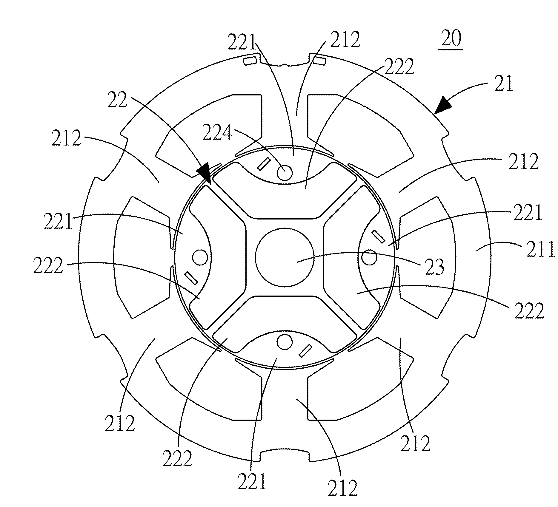
[0022]The present invention improves regular motors, with reference to FIG. 3 and FIG. 4, the present invention comprises of a stator 21, a rotor 22 and a rotation shaft 23;

[0023]The stator 21 further consists of a round shape main body 111 and a plurality number of stator magnetic poles 212, all stator magnetic poles 212 are protruding installed inside the round shape main body 211, a storage space is within each of the stator magnetic pole 212.

[0024]The rotor 22 is installed inside the storage space and form air gap with each stator magnetic pole 212, the rotor 22 has an even number of rotor magnetic poles 221, magnets 222 are inside the rotor magnetic poles 221.

[0025]The rotor magnetic poles 221 are installed in even number, when the number of rotor magnetic poles 221 is P, the number of stator magne...


PUM


Abstract

A motor having more magnets on effective area of the rotor includes a stator, a rotor and a rotation shaft, the rotor has a plurality number of rotor magnetic poles, a magnet is installed inside each of rotor magnetic pole, and a concave arc is on the outer side of each magnet and forms the first, the second and the third surfaces near inside of each magnet. The concave arc connects to the first and the third surfaces with a connecting plan respectively, each connecting plan nears the periphery surface of the rotor. The motor has more magnets on the effective area of the rotor for higher motor efficiency.

Description

BACKGROUND OF THE INVENTION[0001]1. Field of the Invention[0002]The present invention relates to a motor, in particular a motor having more magnets on effective area of the rotor to improve efficiency of the motor thereof.[0003]2. Description of the Related Art[0004]Heretofore, it is known in modem industry that power is needed to drive machinery in rotation or movement in other forms, motors are generally applied as power source; motors can convert electrical power or magnetic energy into mechanical power, motors are widely applied in different variety of industries, electrical appliances, transportation systems, and have become an indispensable device.[0005]Motors can be classified into DC, AC, brushless and brush types, in general, the structure of the motor consists of a rotor and a stator, magnetic flux distribution between rotor and stator activates rotor rotate, the rotation of motor transmits and provides mechanical energy needed. Magnet has magnetic characteristics, permane...

Claims


Application Information

Patent Timeline
Patent Type & Authority Applications(United States)
IPC IPC(8): H02K1/27
CPCH02K1/276H02K29/03
Inventor YU, WEN-HOCHEN, FU-RONGCHU, CHEN-NANLEE, WEI-HSUN
Owner RECHI PRECISION
Why Eureka
Try Eureka