
Process for forming integrated circuits with both split gate and common gate FinFET transistors

a technology of integrated circuits and finfet transistors, which is applied in the field of fin-type mosfet transistors, can solve the problems of increasing circuit cost, increasing die cost, and ics cost generally based on die area, so as to increase die cost, improve readability, and increase die area

Active Publication Date: 2011-02-15
TEXAS INSTR INC
View PDF6 Cites 13 Cited by
  • Summary
  • Abstract
  • Description
  • Claims
  • Application Information

AI Technical Summary

Benefits of technology

This approach enables the integration of dual pass gate devices without increasing die area, providing benefits for SRAM cell designs by optimizing read and write operations and compensating for process corners, while also allowing for back-gate biasing in other circuitry, thus reducing input offset voltage and enhancing circuit performance without additional cost.

Problems solved by technology

However, as well known in the art, the cost for ICs is generally based on their die area.
Accordingly, adding extra transistors to a conventional IC design adds to the cost of the circuit.
This is typically not an option in substrates comprising conventional bulk silicon due to the accompanying increase in die area and resulting increase in die cost.

Method used


Image

  • Process for forming integrated circuits with both split gate and common gate FinFET transistors
  • Process for forming integrated circuits with both split gate and common gate FinFET transistors
  • Process for forming integrated circuits with both split gate and common gate FinFET transistors

Examples


Embodiment Construction

[0015]The present invention is described with reference to the attached figures, wherein like reference numerals are used throughout the figures to designate similar or equivalent elements. The figures are not drawn to scale and they are provided merely to illustrate the instant invention. Several aspects of the invention are described below with reference to example applications for illustration. It should be understood that numerous specific details, relationships, and methods are set forth to provide a full understanding of the invention. One having ordinary skill in the relevant art, however, will readily recognize that the invention can be practiced without one or more of the specific details or with other methods. In other instances, well-known structures or operations are not shown in detail to avoid obscuring the invention. The present invention is not limited by the illustrated ordering of acts or events, as some acts may occur in different orders and / or concurrently with o...


PUM


Abstract

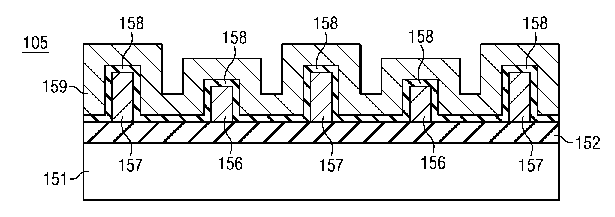
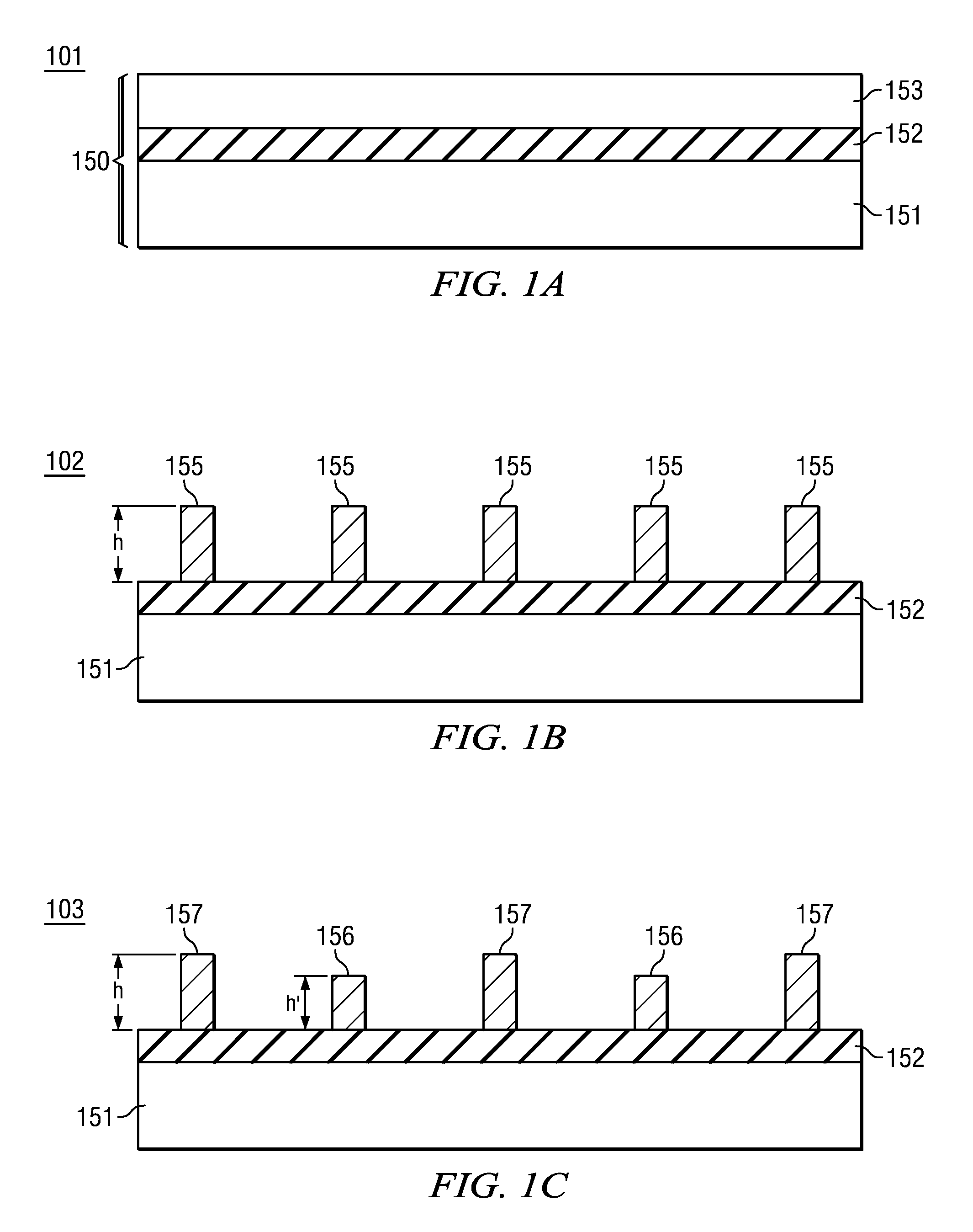
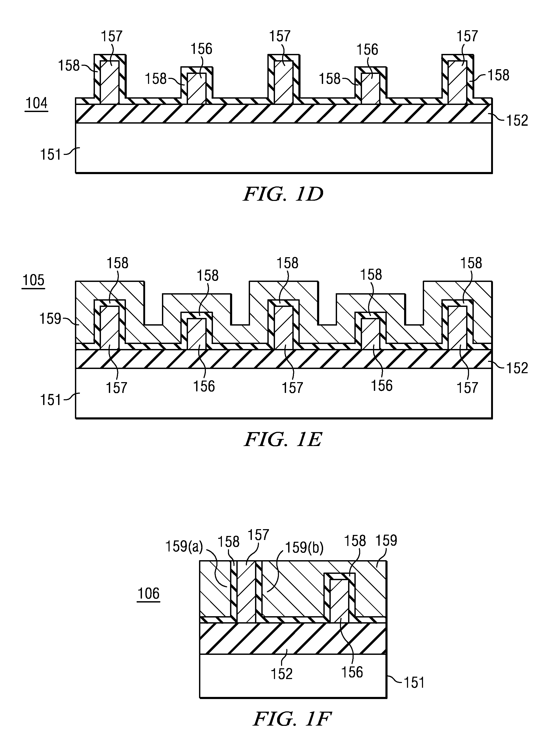
A method is disclosed for forming an integrated circuit including a common gate FinFET device and a split gate FinFET device. Taller fins and shorter fins of different heights are formed in a semiconductor surface. Layers of gate dielectric material and gate electrode material are formed over tops and sides of the fins. The gate electrode material layer is planarized using chemical-mechanical polishing to remove the gate electrode material from the tops of the taller fins, leaving the gate electrode material over the tops of the shorter fins. The planarized material is patterned to form split (dual) gate structures on the sides of the taller fins and common gate structures on the tops and sides of the shorter fins.

Description

FIELD OF THE INVENTION[0001]Embodiments of the present invention generally relate to MOSFET transistors and more particularly to the fin-type MOSFET transistors commonly known as FinFETs, and to methods for forming integrated circuits (ICs) including at least one fin which provides a split gate FinFET and at least one fin which provides a conventional common gate FinFET.BACKGROUND[0002]Field effect transistors (FETs) can be formed in a variety of ways to serve a variety of purposes for integrated circuits and other devices. Commonly, FETs are formed as “planar” devices in many integrated circuits, i.e., as devices in which the conduction channel has width and length extending in a direction parallel to the major surface of a substrate. FETs can be formed in a semiconductor-on-insulator (SOI) layer of a substrate or in a bulk semiconductor substrate.[0003]Frequently, FETs are formed having a non-planar conduction channel, in order to serve a special purpose. In such non-planar FETs, ...

Claims


Application Information

Patent Timeline
Patent Type & Authority Patents(United States)
IPC IPC(8): H01L21/8234H10B10/00
CPCG11C11/412H01L21/845H01L27/1108H01L27/1211H01L29/66795H10B10/125
Inventor MARSHALL, ANDREWHOUSTON, THEODORE WARREN
Owner TEXAS INSTR INC
Learn More