Virtual image display device and manufacturing method of virtual image display device

a display device and virtual image technology, applied in static indicating devices, instruments, optics, etc., can solve the problems of eyelid strain and stress, and achieve the effect of suppressing stress on observers and reducing eye strain on observers

Active Publication Date: 2013-04-11
SEIKO EPSON CORP
View PDF6 Cites 58 Cited by
  • Summary
  • Abstract
  • Description
  • Claims
  • Application Information

AI Technical Summary

Benefits of technology

[0007]An advantage of some aspects of the invention is to provide a virtual image display device that can reduce strain on eyes of observers during use and suppress stress on the observers even in the long periods of use.
[0009]In the virtual image display device, the tilt angle adjustment unit is provided and the adjustment with respect to the direction of the image optical axis, i.e., the angle adjustment of the direction of eyes of the observer can be performed with reference to the front vision direction. Thereby, for example, the direction of eyes of the observer may be naturally adjusted for downward observation for the observer. By the angle adjustment of the direction of eyes of the observer, compared to the case where observation is performed in a state in which the observer sees in the front vision direction, the strain on the eyes of the observer may be reduced and the stress on the observer may be suppressed even when the device is used over a long period.
[0012]In still another specific aspect of the invention, the projection optical axis adjustment unit is a cushion member provided in a part corresponding to a location of an ear of the observer of the frame. In this case, by adjusting the size of the cushion member, the tilt of the projection optical axis of the projection system may be adjusted, and thus, the tilt of the image optical axis of the image light may be easily adjusted.
[0013]In yet another specific aspect of the invention, the tilt angle adjustment unit is a shift structure in which a display center axis of the image display unit extending in parallel to the projection optical axis of the projection system is shifted in a direction perpendicular to the projection optical axis of the projection system. In this case, by adjusting an amount of shift in the shift structure, the tilt of the image optical axis of the image light may be easily adjusted.
[0019]In a further specific aspect of the invention, the tilt angle adjustment unit tilts a tilt angle of the image optical axis of the image light by seven degrees or more with respect to the front vision direction. In this case, the angle of the direction of eyes of the observer may be naturally lowered to the extent necessary for reduction of the strain on the eyes of the observer.

Problems solved by technology

However, the human eye has a structure of opening wide for observation in the state in which the observer looks straight ahead, and the eyelids of the observer take heavy strain.
The head-mounted displays are intended for continuous use in long periods, such stress may be particularly problematic.

Method used


Image

  • Virtual image display device and manufacturing method of virtual image display device
  • Virtual image display device and manufacturing method of virtual image display device
  • Virtual image display device and manufacturing method of virtual image display device

Examples


first embodiment

[0032]As below, a virtual image display device according to the first embodiment of the invention will be explained in detail with reference to the drawings.

A. Appearance of Virtual Image Display Device etc.

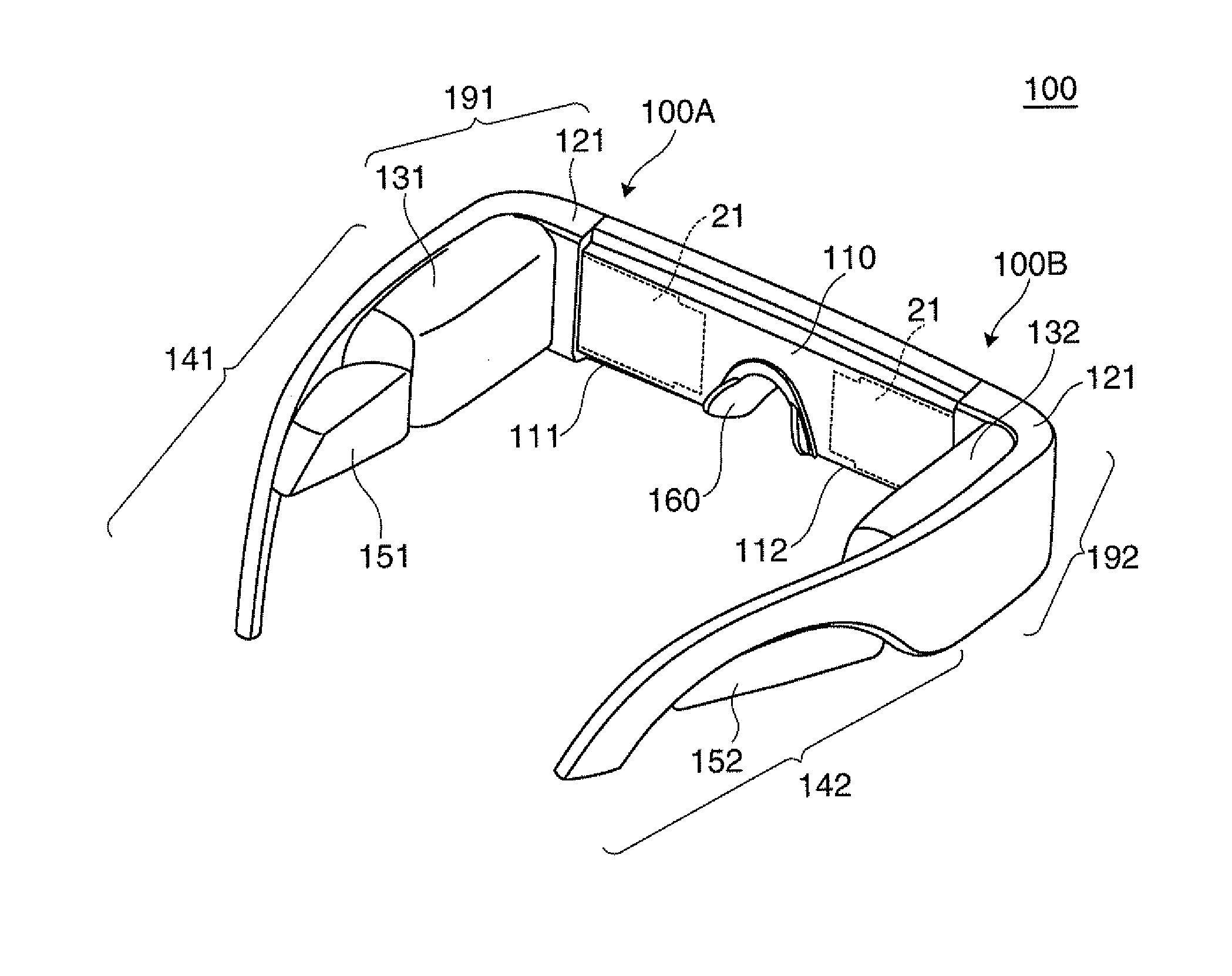
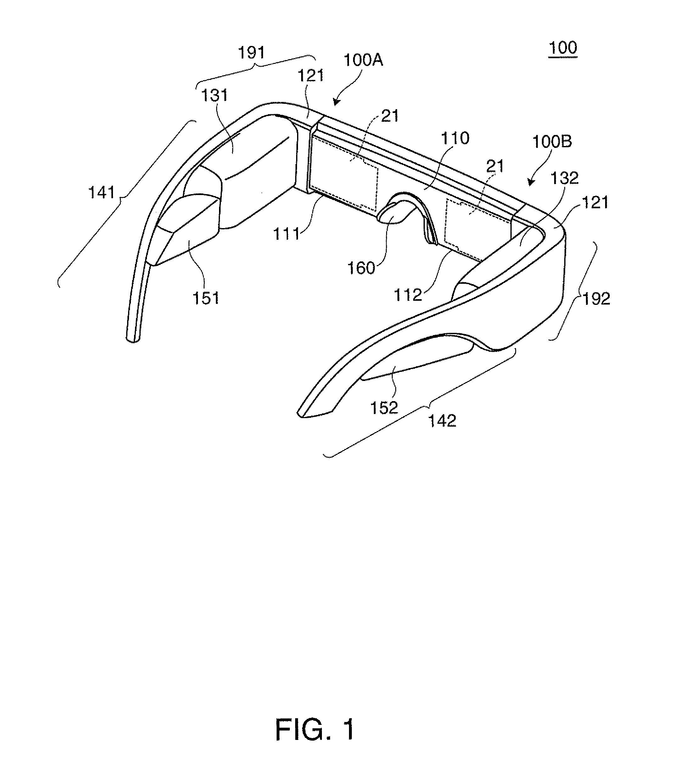
[0033]A virtual image display device 100 of the embodiment shown in FIG. 1 is a head-mounted display having an appearance of spectacles, and enables an observer wearing the virtual image display device 100 to recognize image light by a virtual image and observe an external image in a see-through manner. The virtual image display device 100 includes an optical panel 110 that covers the view of observer, a frame 121 that supports the optical panel 110 etc., first and second drive parts 131, 132 added to parts from front cover parts 191, 192 to temples 141, 142 of the frame 121. Specifically, the frame 121 has ear cushion members 151, 152 in parts adjacent to the first and second drive parts 131, 132 of the temples 141, 142. That is, the frame 121 also supports the respective drive ...

second embodiment

[0074]As below, a virtual image display device of the second embodiment will be explained with reference to FIGS. 8A to 8D. Note that the virtual image display device 200 of the embodiment is a modified example of the virtual image display device 100 of the first embodiment and the parts or items without particular explanation are the same as those of the first embodiment, and only FIGS. 8A to 8C corresponding to FIGS. 7A to 7C and FIG. 8D schematically showing optical paths are shown and illustration and explanation of the whole configuration etc. will be omitted.

[0075]As shown in FIG. 8A, in the virtual image display device 200 of the embodiment, the image display unit 11, the projection system 12, the light guide member 21, etc. forming the image forming device 10 do not tilt forward unlike those in the virtual image display device 100. In other words, the first optical axis AX1 of the projection system 12, i.e., the projection optical axis is in parallel to the front vision dire...

third embodiment

[0082]As below, a virtual image display device of the third embodiment will be explained with reference to FIG. 9A, etc. Note that the virtual image display device of the embodiment is a modified example of the virtual image display device 100 of the first embodiment and the parts or items without particular explanation are the same as those of the first embodiment, and illustration and explanation of the whole configuration etc. will be omitted.

[0083]In the embodiment, as shown in FIGS. 9A and 9B, a light guide member 321 forming the virtual image display device of the embodiment has an image extraction surface adjustment structure PP tilted so that the normal direction of the fourth reflection surface 21d may have a component with respect to the Y direction. Thereby, the image optical axis of the image light reflected and output by the fourth reflection surface 21d may be tilted. Note that the appearance and the structure of the virtual image display device of the embodiment are d...


PUM


Abstract

In a virtual image display device, direction adjustment of an image optical axis, i.e., angle adjustment of a direction of eyes of an observer can be performed by providing a cushion member or adjusting an amount of shift between an image display unit and a projection system, and thereby, strain on eyes of an observer in use may be reduced. Even when the virtual image display device is used over a long period, for example, stress on the observer may be suppressed.

Description

BACKGROUND[0001]1. Technical Field[0002]The present invention relates to a virtual image display device such as a head-mounted display mounted on a head.[0003]2. Related Art[0004]Recently, as virtual image display devices that enable formation and observation of virtual images like head-mounted displays, various devices of a type of guiding image light from a display element to eyes of an observer using a light guide plate have been proposed (see Patent Document (JP-A-2008-172367) and Patent Document 2 (JP-A-2000-249969)).[0005]Not only in the cases of Patent Documents 1 and 2, but many head-mounted displays generally have shapes like spectacles and sunglasses in view of downsizing and design of the devices. In the head-mounted display having the configuration, when image light is propagated along the shape, the image light is output with a direction of a center optical axis as the center thereof at nearly horizontal zero degrees. The observer continues to observe images while keepi...

Claims


Application Information

Patent Timeline
Patent Type & Authority Applications(United States)
IPC IPC(8): G09G5/00
CPCG02B2027/0181G02B27/0176G02B27/0172G02B2027/0178
Inventor TOTANI, TAKAHIROTAKAGI, MASAYUKIMIYAO, TOSHIAKIKOMATSU, AKIRATAKEDA, TAKASHIFUJISHIRO, TAKESHI
Owner SEIKO EPSON CORP
Why Eureka
Try Eureka