Ultra thin light scanning apparatus for portable information device

Inactive Publication Date: 2013-04-11
GWANGJU INST OF SCI & TECH
View PDF8 Cites 8 Cited by
  • Summary
  • Abstract
  • Description
  • Claims
  • Application Information

AI Technical Summary

Benefits of technology

[0017]According to the present invention, since light emitted from a light emitting device is totally reflected from an object-side surface, the loss of the light is minimized. Thus, even when the light emitting device has a small capacity, a large area can be sufficiently scanned.
[0018]In addition, light refracted and scattered by the object-side surface is not used to form an image, and only totally reflected light is used to form an image. Thus, an image formed according to the present invention has a higher contrast ratio and higher resolution than those of an image forme

Problems solved by technology

Input methods using a keypad are sufficient for limited and simple functions of typical information devices, such as input of a phone number or tra

Method used


Image

  • Ultra thin light scanning apparatus for portable information device
  • Ultra thin light scanning apparatus for portable information device
  • Ultra thin light scanning apparatus for portable information device

Examples


Example

BEST MODE

[0027]Preferred embodiments of the present invention will be described below in detail with reference to the accompanying drawings. In the following description and attached drawings, like elements are substantially denoted by like reference numerals, even in the case that they are illustrated in different drawings. Moreover, detailed descriptions related to well-known functions or configurations will be ruled out in order not to unnecessarily obscure subject matters of the present invention.

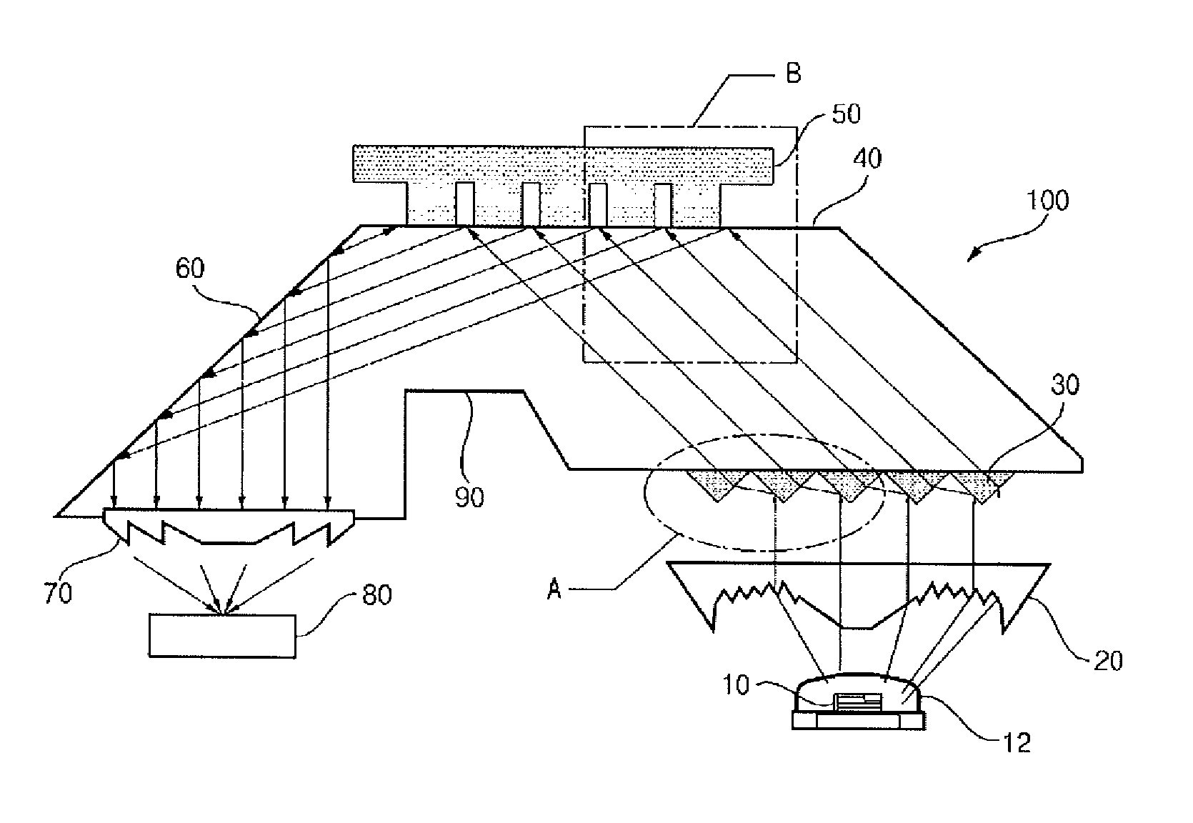
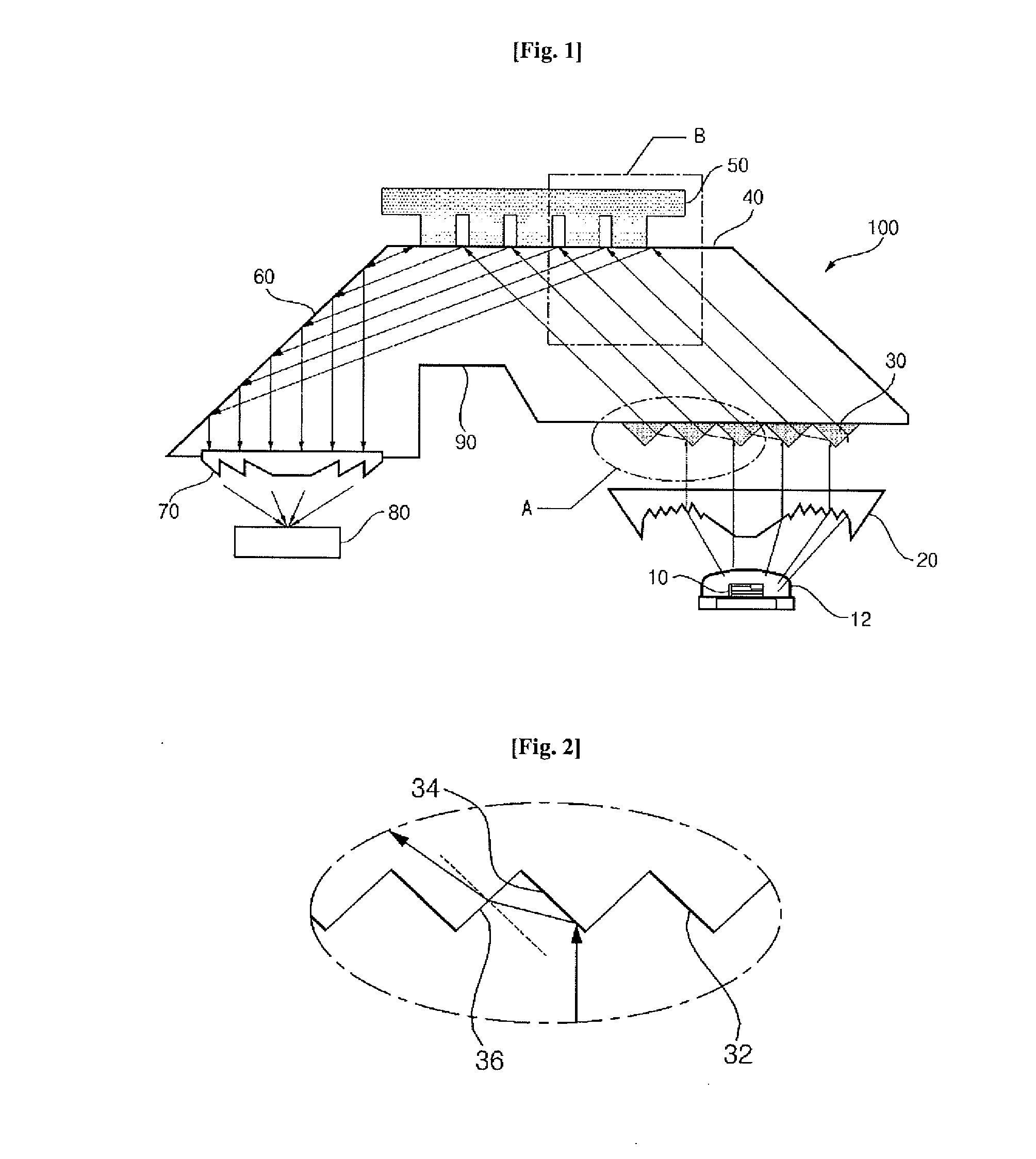
[0028]FIG. 1 is a schematic view illustrating a configuration of an optical scanning device according to an embodiment of the present invention. FIG. 2 is an enlarged view illustrating a portion A of FIG. 1. FIG. 3 is an enlarged view illustrating a portion B of FIG. 1.

[0029]Referring to FIG. 1, an optical scanning device according to the current embodiment may include: a light emitting device 10 that emits light to sense an object 50; a condensing lens 20 that collects the light emitte...


PUM


Abstract

Disclosed is an ultra thin optical scanning device for a portable information device, which includes an LED as a light source and totally reflects light from an object-side surface to form an image, thereby increasing a contrast ratio of the image and improving the resolution thereof. The ultra thin optical scanning device includes a light emitting device that emits light for sensing an object, an object-side surface contacting the object and totally reflecting the light emitted from the light emitting device, an image formation part collecting the light totally reflected by the object-side surface, and transmitting the light, and a light receiver part forming an image by using the light transmitted by the image formation part.

Description

TECHNICAL FIELD [0001]The present invention disclosed herein relates to an optical scanning device, and more particularly, to an ultra thin optical scanning device including a light emitting diode (LED) as a light source and totally reflecting light from an object-side surface to form an image, thereby increasing a contrast ratio of the image and improving the resolution thereof.BACKGROUND ART [0002]Small information devices may receive information through a keypad and be controlled through the keypad. Input methods using a keypad are sufficient for limited and simple functions of typical information devices, such as input of a phone number or transmission of a text.[0003]Recently developed optical scanning devices recognize a fingerprint or a bar code for improving user convenience and security. For example, a small pointing device using a finger skin is disclosed in Korean Patent Publication No. 10-2005-0002463. Light, emitted from a light emitting device, passes through a transpa...

Claims


Application Information

Patent Timeline
IPC IPC(8): H04N1/028G06F3/03
CPCG06F3/0304H04N1/02815G06F2203/04109H04N1/02825G06F3/042H04N1/00522
Inventor LEE, SUN KYUJOO, JAE YOUNGLEE, CHA BUMWOO, DO KYUN
Owner GWANGJU INST OF SCI & TECH
Why Eureka
Try Eureka