Camera Module

a technology of camera module and holder device, which is applied in the direction of mounting, instruments, camera body details, etc., can solve the problems of polluting the production environment and unwanted particle generation

Inactive Publication Date: 2013-04-11
LARGAN PRECISION
View PDF3 Cites 5 Cited by
  • Summary
  • Abstract
  • Description
  • Claims
  • Application Information

AI Technical Summary

Benefits of technology

[0008]According to the first embodiment of the present invention, a camera module includes a base board, a holder, a conductive circuit, a camera lens and an electric-controlled light permissible element. There is a light sensing element disposed on the base board, and a control signal is issued from the base board. The holder is connected to the base board and is arranged on the outer side of the base board surrounding the light sensing element. The conductive circuit is arranged on the holder and is electrically connected to the base

Problems solved by technology

Furthermore, during the assembling process of the coupling elements 160 of the conventional camera module 100, the coupling elements 160 will have movements with

Method used


Image

  • Camera Module
  • Camera Module
  • Camera Module

Examples


first embodiment

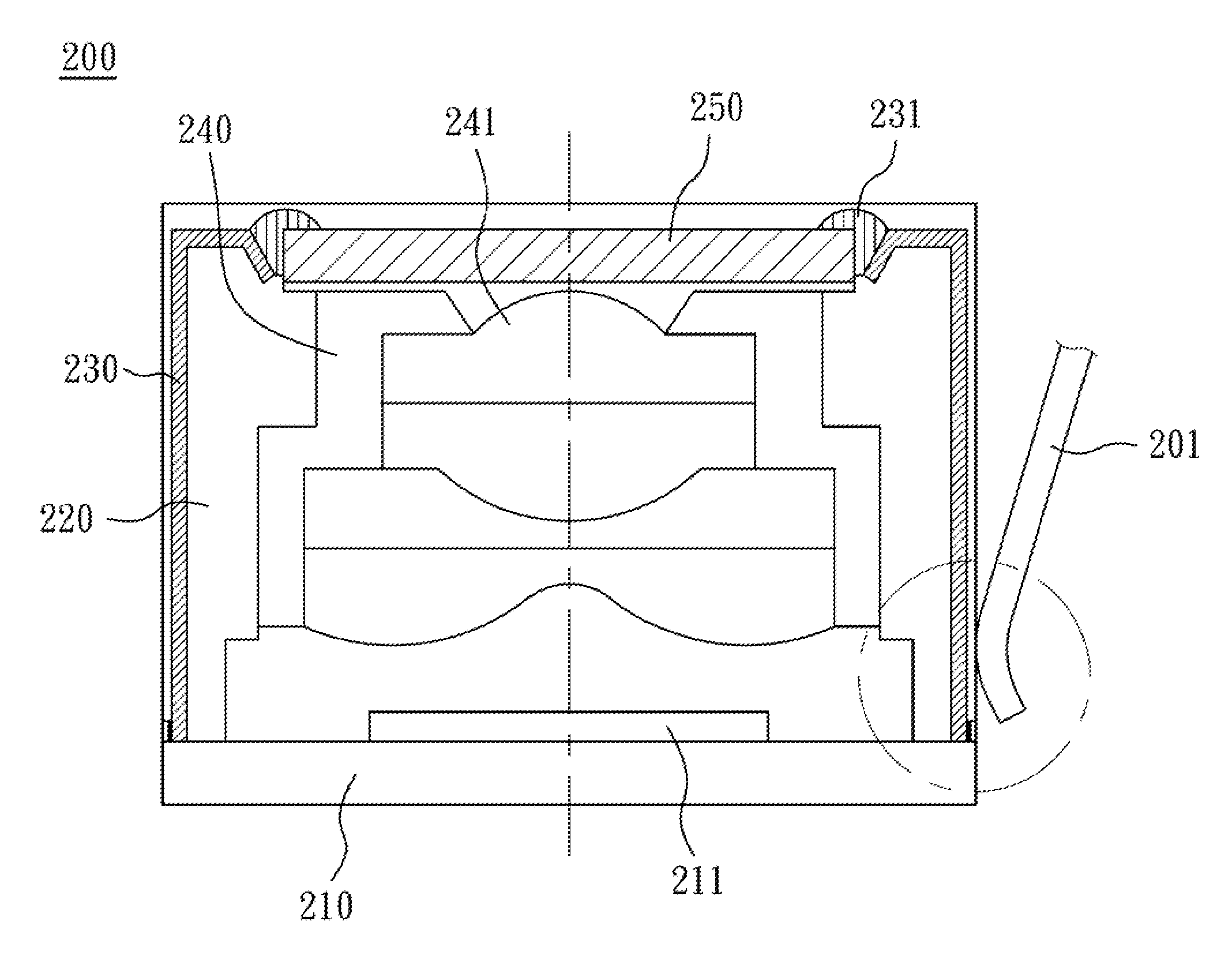
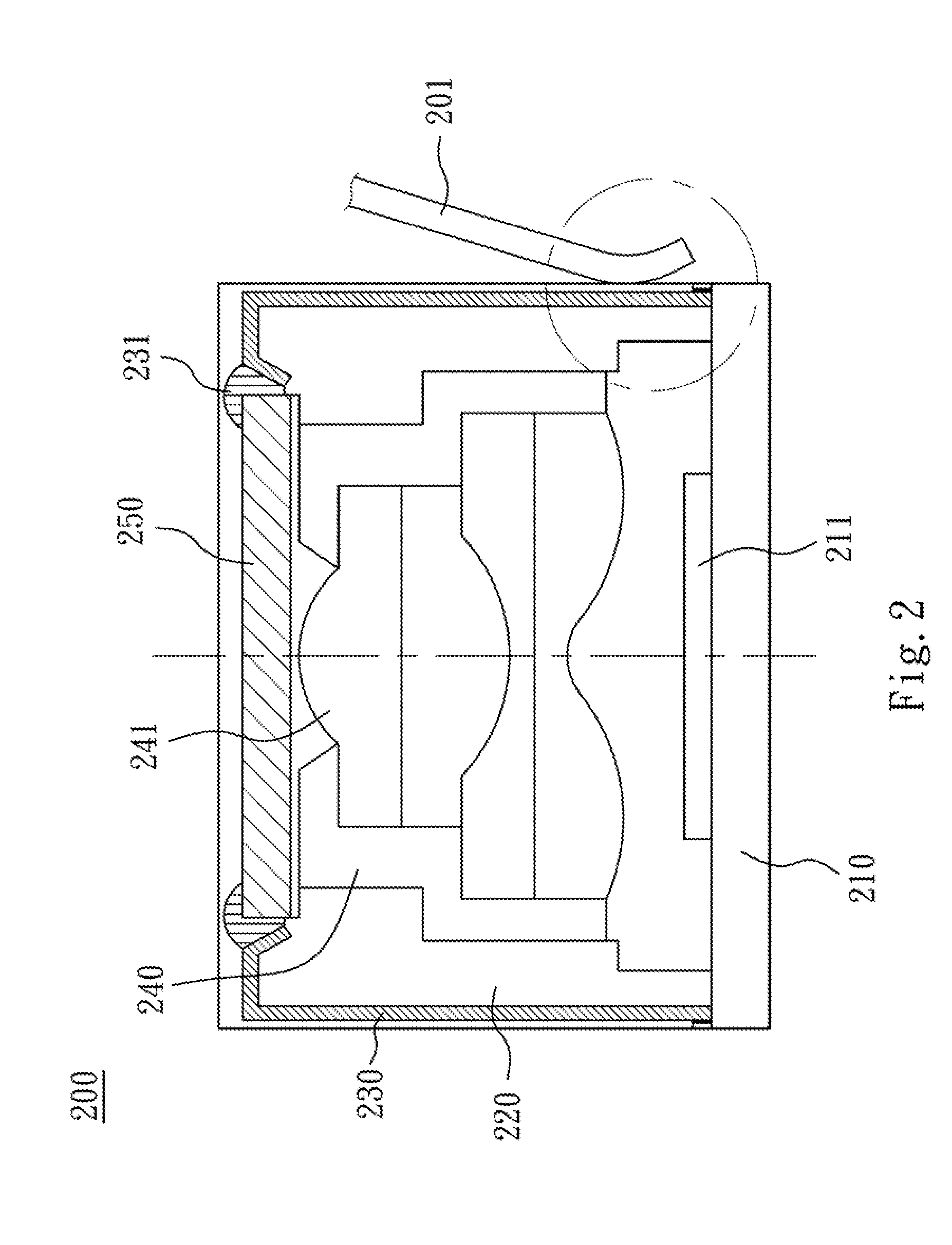
[0017]FIG. 2 is a schematic structure diagram of a camera module according to the present invention. FIG. 3 is a partially enlarged diagram of the camera module shown in FIG. 2. As shown in FIG. 2 and FIG. 3, the camera module 200 includes a base board 210, a holder 220, a conductive circuit 230, a camera lens 240 and an electric-controlled light permissible element 250. There is a light sensing element 211 disposed on the base board 210, and a control signal is issued from the base board 210. The holder 220 is connected to the base board 210 and is arranged on the outer side of the base board surrounding the light sensing element 211.

[0018]The conductive circuit 230 is arranged on the holder 220 and is electrically connected to the base board 210 for receiving the control signal, in which the conductive circuit 230 does not extend out of a surface of the holder 220. The phrase “the conductive circuit 230 does not extend out of a surface of the holder 220” as used herein may include...

second embodiment

[0022]FIG. 4 is a schematic structure diagram of a camera module according to the present invention. As shown in FIG. 4, the camera module 300 includes a base board 310, a holder 320, a conductive circuit 330, a camera lens 340 and an electric-controlled light permissible element 350. The camera module 300 of the present embodiment and the camera module 200 of the aforementioned embodiment are substantially similar, but are different in the relative positions of the light sensing elements 211, 311, the camera lenses 240, 340, and the electric-controlled light permissible elements 250, 350.

[0023]The camera module 200 of the aforementioned embodiment arranges the camera lens 240 between the electric-controlled light permissible element 250 and the light sensing element 211, but the camera module 300 of the present embodiment arranges the electric-controlled light permissible element 350 between the camera lens 340 and the light sensing element 311. The differences between the two embo...

third embodiment

[0025]FIG. 5 is a schematic structure diagram of a camera module of the present invention. FIG. 6 is a partially enlarged diagram of the camera module shown in FIG. 5. As shown in FIG. 5 and FIG. 6, the camera module 400 includes a base board 410, a holder 420, a conductive circuit 430, a camera lens 440 and an electric-controlled light permissible element 450. Because of many similarities between the camera module 400 of the present embodiment and the camera module 200 of the aforementioned embodiment, only the differences there between are described hereinafter.

[0026]The conductive circuit 430 is arranged on the holder 420 and is electrically connected to the base board 410 for receiving the control signal, in which the conductive circuit 430 does not extend out of a surface of the holder 420. The present embodiment will describe the situation that the conductive is circuit 430 extends as far as the boundary aligned with a surface of the holder 420. The conductive circuit 430 of ...


PUM


Abstract

A camera module includes a base board, a holder, a conductive circuit, a camera lens and an electric-controlled light permissible element. A light sensing element is disposed on the base board, and a control signal is issued from the base board. The holder is connected to the base board and arranged on the light sensing element. The conductive circuit is arranged on the holder and electrically connected to the base board for receiving the control signal. The conductive circuit does not extend out of a surface of the holder. The camera lens has a lens and arranged with respect to the light sensing element. The electric-controlled light permissible element is electrically connected to the conductive circuit and arranged with respect to the light sensing element. The electric-controlled light permissible element changes its surface according to the control signal, thereby adjusting a focal length of the camera lens.

Description

RELATED APPLICATIONS[0001]The application claims priority to Taiwan Application Serial Number 100136063, filed Oct. 5, 2011, which is herein incorporated by reference.BACKGROUND[0002]1. Technical Field[0003]The present disclosure relates to a photography module device. More particularly, the present disclosure relates to a holder device of a camera lens.[0004]2. Description of Related Art[0005]Refer to FIG. 1, FIG. 1 is a schematic diagram of a conventional camera module. As shown in FIG. 1, a camera module 100 includes a camera lens 110, an electric-controlled element 120, a first holder 130, a second holder 140, a pair of metal elements 150 and a pair of coupling elements 160.[0006]The camera lens 110 has at least one lens 111. The electric-controlled element 120 is a liquid lens. The first holder 130 is used to hold the camera lens 110 and the electric-controlled element 120. The second holder 140 is used to hold the first holder 130, and the second holder 140 has a pair of condu...

Claims


Application Information

Patent Timeline
IPC IPC(8): G03B17/00G02B7/04
CPCG02B7/08
Inventor HUANG, CHEN-YI
Owner LARGAN PRECISION
Why Eureka
Try Eureka