

Method for data backup, device and system
- Summary
- Abstract
- Description
- Claims
- Application Information
AI Technical Summary
Benefits of technology
Problems solved by technology
Method used
Image

Examples
Embodiment Construction
[0025]In order that a person skilled in the art can better understand the solutions of the embodiments of the present invention, the embodiments of the present invention are further described in details with reference to the drawings and examples.
[0026]In order to facilitate the understanding by a person skilled in the art, the virtualized data center will be briefly introduced before the present invention.
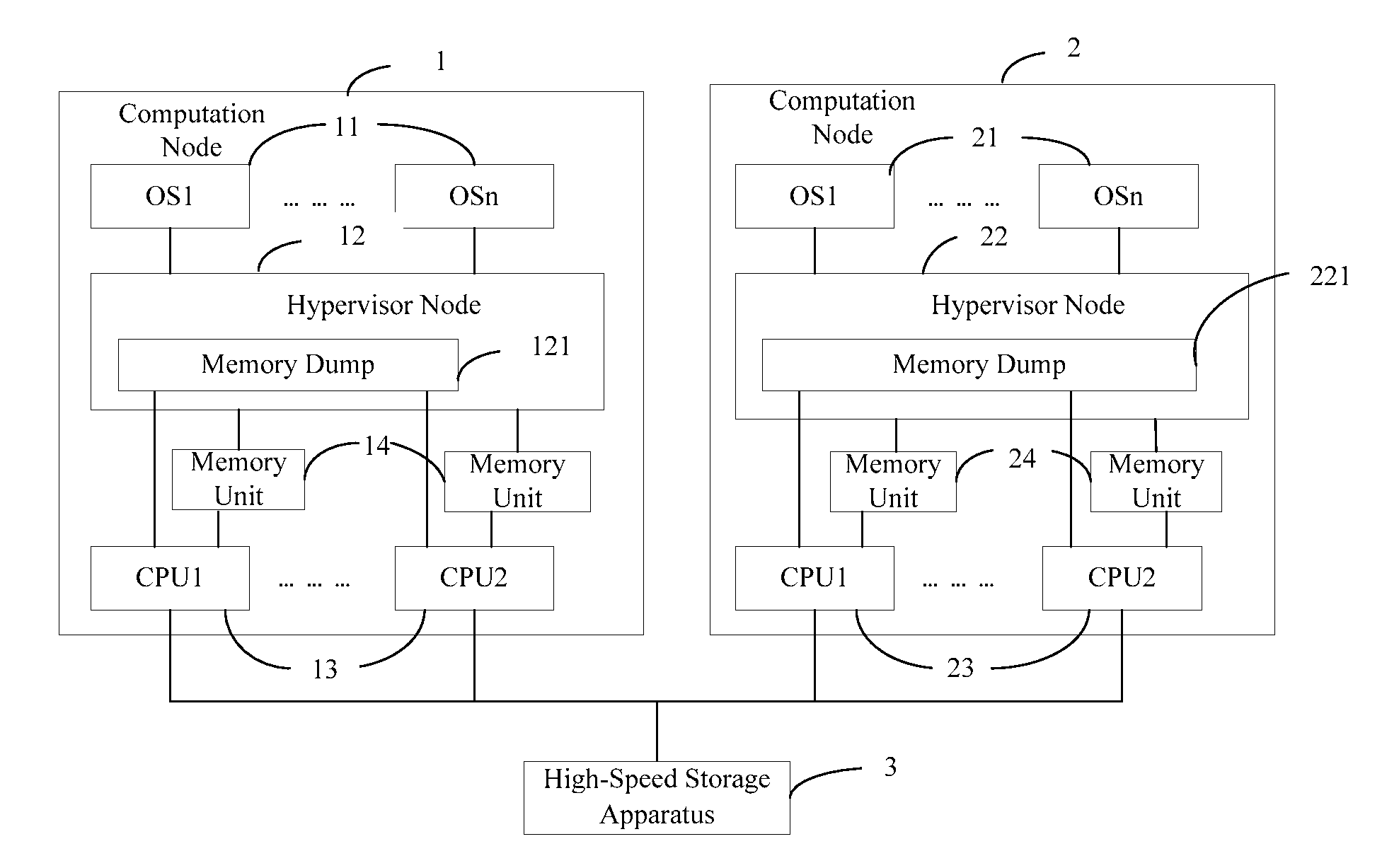
[0027]The virtualized data center is usually composed of at least two computation nodes, at each of which a hypervisor (called as hypervisor node in the present invention) runs. The hypervisor abstracts and reorganizes the physical memory, the processor and the I / O resource of the computation nodes in the data center, and create a plurality of virtual machines. Thus the hypervisor may be regarded as a resource ownership conversion module. In the virtualized data center, only the hypervisor can access all the computation node physical resources.
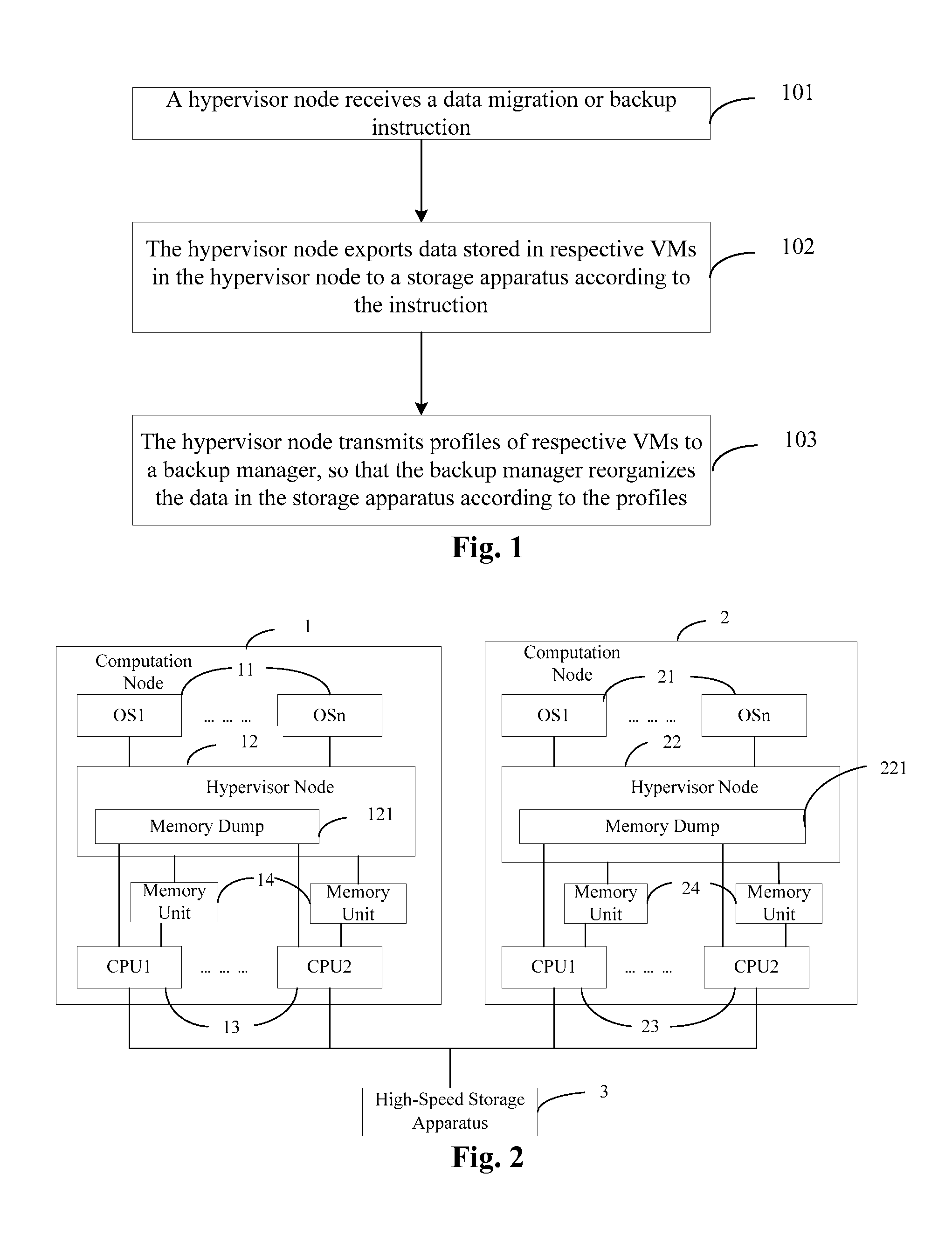
[0028]Please refer to FIG. 1, which i...
PUM
 Abstract
Description
Claims
Application Information