Hair remover

a hair removal and hair technology, applied in the field of hair removal, can solve the problems of insufficient shaving of hair growing on such an area, inability to easily introduce body hair, interference with irregularities, etc., and achieve the effect of reducing the possibility of body hair being insufficiently shaved, improving the convenience of hair removal, and reducing the possibility of hair removal

Active Publication Date: 2013-04-18
PANASONIC INTELLECTUAL PROPERTY MANAGEMENT CO LTD
View PDF47 Cites 10 Cited by
  • Summary
  • Abstract
  • Description
  • Claims
  • Application Information

AI Technical Summary

Benefits of technology

[0011]This configuration makes it possible to perform removing body hair without occurrence of the interference with the body by means of desirably selecting the direction of the head unit (cutting width), so as to reduce the possibility that body hair is insufficiently shaved. As a result, the convenience of the hair remover can be improved. In addition, the hair remover can be downsized by reducing the protrusion of the head unit with respect to the outer periphery of the main unit.

Problems solved by technology

For this reason, when removing body hair growing on an area having irregularities around, such as a biological surface of a base of arm or leg, the main unit itself or a human-hand grasping the main unit may interfere with the irregularities.
As a result, the body hair is not easily introduced between the fixed and movable blades, and there is a possibility that hair growing on such an area is insufficiently shaved.

Method used


Image

  • Hair remover
  • Hair remover
  • Hair remover

Examples


Embodiment Construction

[0029]An embodiment of the present invention will be explained below referring to attached Figures.

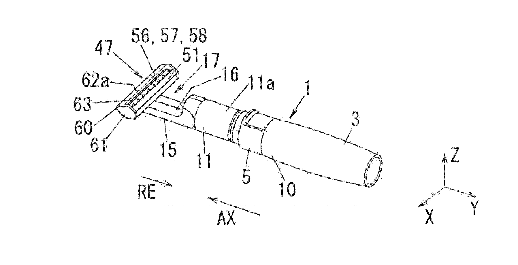
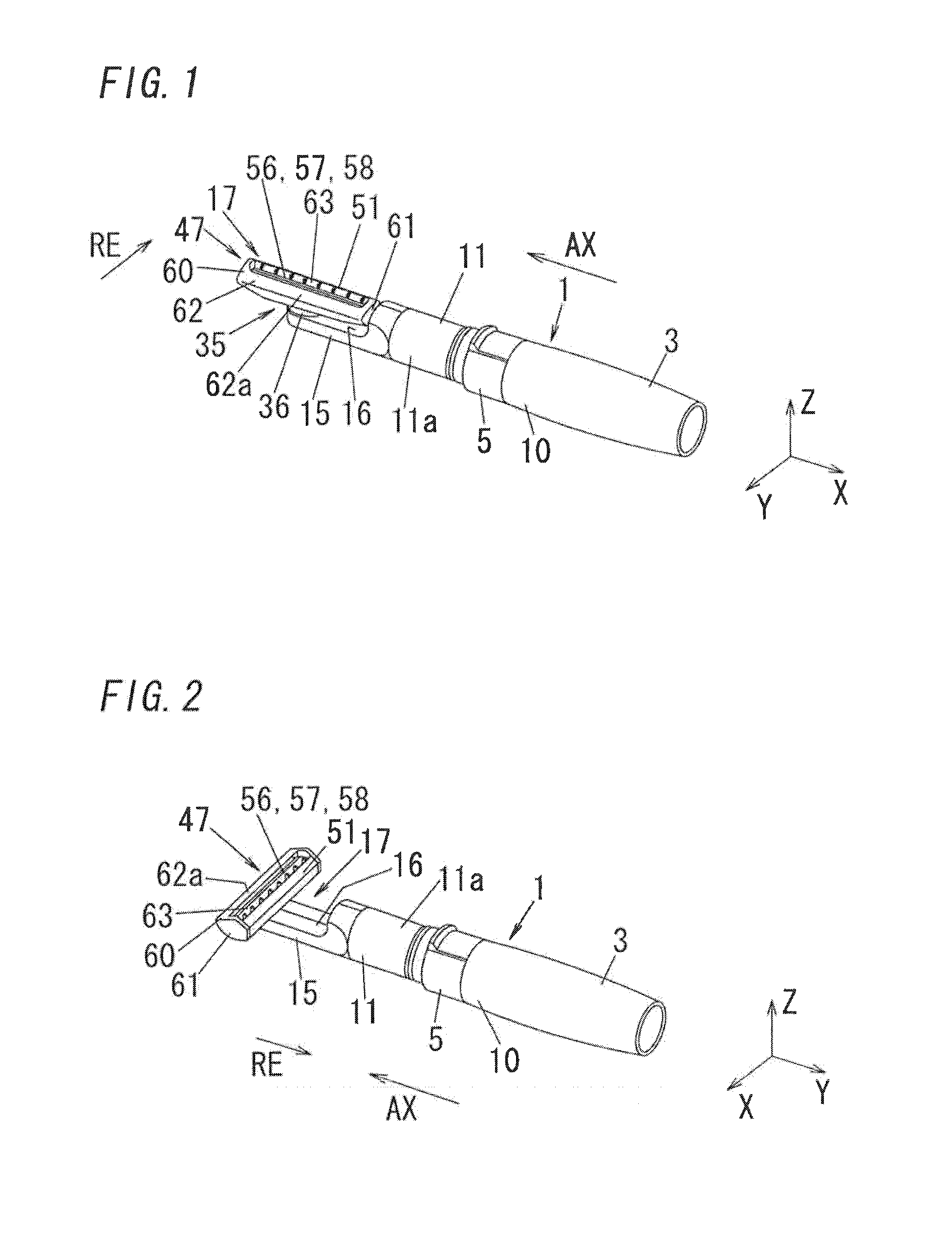
[0030]As shown in FIG. 1, a hair remover according to the present embodiment includes: a main unit 1 having an electric power source built in; a head unit 47 having a blade 56 for removing hair; a drive unit 20 (see FIG. 5) for driving the head unit 47; and a cap 6 (see FIG. 16) detachably attached to the main unit 1 so as to cover the head unit 47.

[0031]As shown in FIG. 4, the main unit 1 includes: a power supply portion 7 configured to be equipped with a battery cell (not shown) of an electric source; a housing 5 in which the drive unit 20 is housed; a seal holder 4 for coupling the housing 5 and the power supply portion 7; and a battery cover 3 for replacing the battery cell. The battery cover 3 is detachably attached to the seal holder 4 so as to cover to conceal the power supply portion 7. Then, a casing of the main unit 1 is formed into a hollow cylinder shape through the housing...


PUM


Abstract

A hair remover comprising: a main unit having a gripper; a head unit having a blade for removing body hair; and a drive unit for driving said blade. Said main unit is provided in one end with an extension portion configured to support said head unit, an extending direction of said extension portion from said one end being defined as an extension direction. Said hair remover is configured to have a first state where the longitudinal direction of said head unit is parallel to the extension direction and a second state where the longitudinal direction of said head unit is perpendicular to the extension direction. Said hair remover is configured so that outer periphery of said head unit is located so as to be flush with or is located within outer periphery of said main unit when viewed from the extension direction.

Description

TECHNICAL FIELD[0001]The invention relates to a hair remover configured to drive a blade to cut body hair.BACKGROUND ART[0002]There used to be a hair remover which includes a comb-shaped fixed blade and a comb-shaped movable blade. This hair remover includes a head unit having the fixed blade and the movable blade, and a main unit having an extension portion provided at one end of its gripper. The head unit is arranged at the tip of the extension portion. When contacting the head unit with a haired biological surface and then introducing the body hair between the fixed and movable blades, the introduced body hair is sheared (cut off) with the fixed and movable blades. The hair remover thereby cuts to remove the body hair on the biological surface. For instance, Japanese Patent Application Laid-Open No. 2002-369979 discloses one of such a hair remover in which comb-shaped fixed and movable blades are arranged in parallel with an extension direction of the extension portion, and Japan...

Claims


Application Information

Patent Timeline
Patent Type & Authority Applications(United States)
IPC IPC(8): B26B21/52
CPCB26B19/063B26B19/28B26B19/02B26B19/048
Inventor SHIMIZU, HIROAKIHASHIGUCHI, TETSURO
Owner PANASONIC INTELLECTUAL PROPERTY MANAGEMENT CO LTD
Why Eureka
Try Eureka