Punch device

a technology of punching device and punching belt, which is applied in the direction of metal working device, metal working apparatus, feeding device, etc., can solve the problems of difficult to manually remove significant amount of time to take away the punched work piece, and low efficiency of using the existing punching device or press

Inactive Publication Date: 2013-04-18
FU TAI HUA IND SHENZHEN +1
View PDF8 Cites 20 Cited by
  • Summary
  • Abstract
  • Description
  • Claims
  • Application Information

AI Technical Summary

Problems solved by technology

However, after the punching process, the punched work pieces are often difficult to be taken or removed from the conveyer belt manually.
It often requires significant amount of time to take away the punched work pieces, thereby causing low efficiency using the existing punch device or press.

Method used


Image

  • Punch device
  • Punch device
  • Punch device

Examples


Embodiment Construction

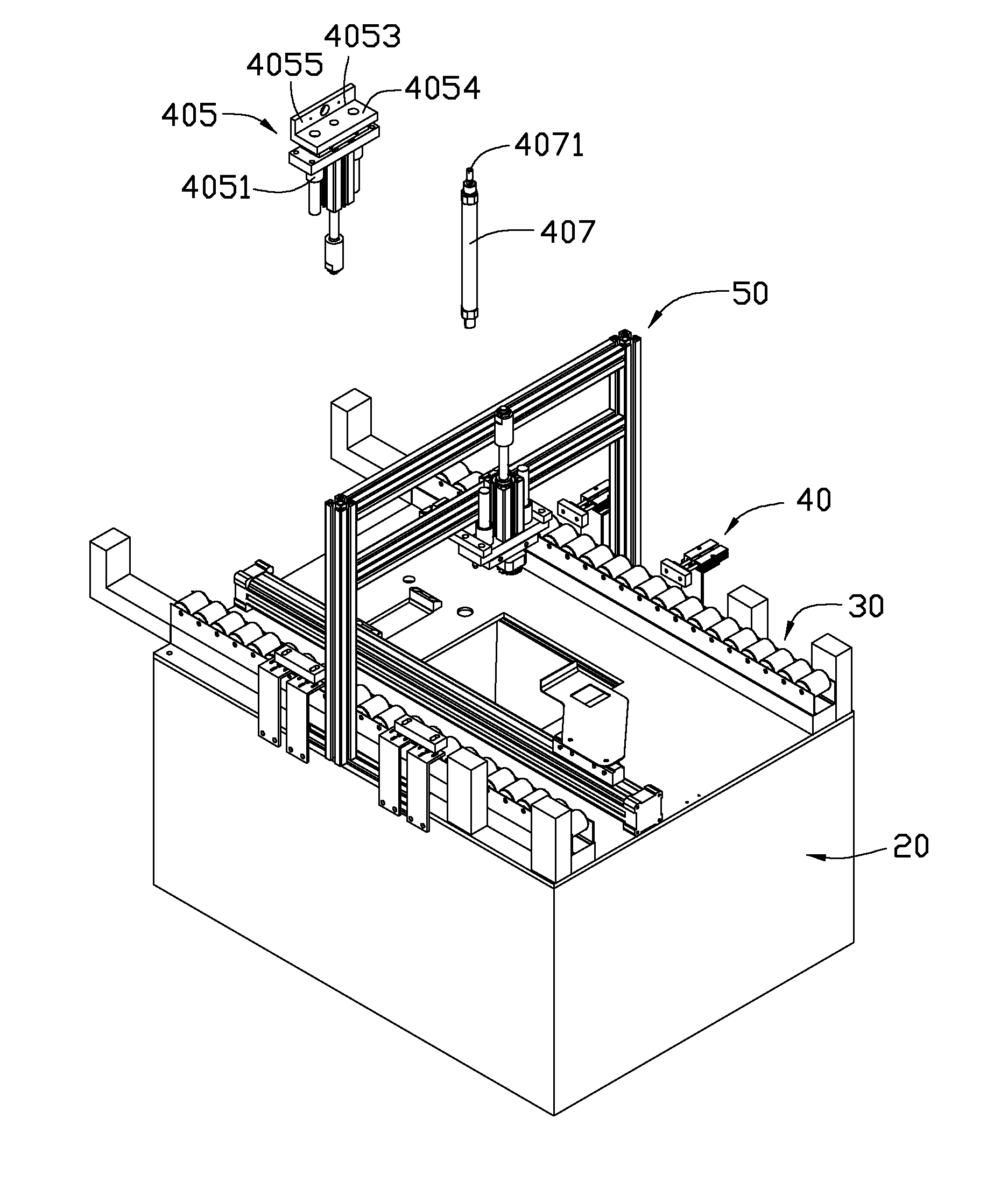
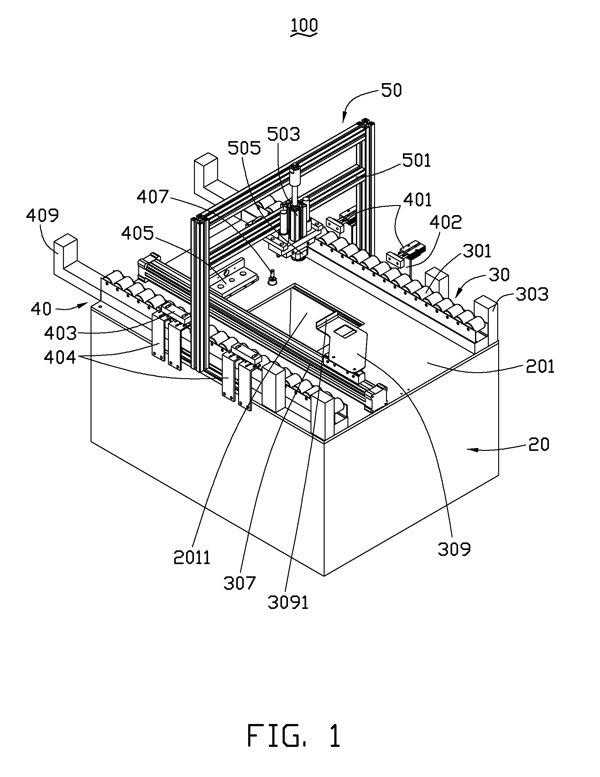
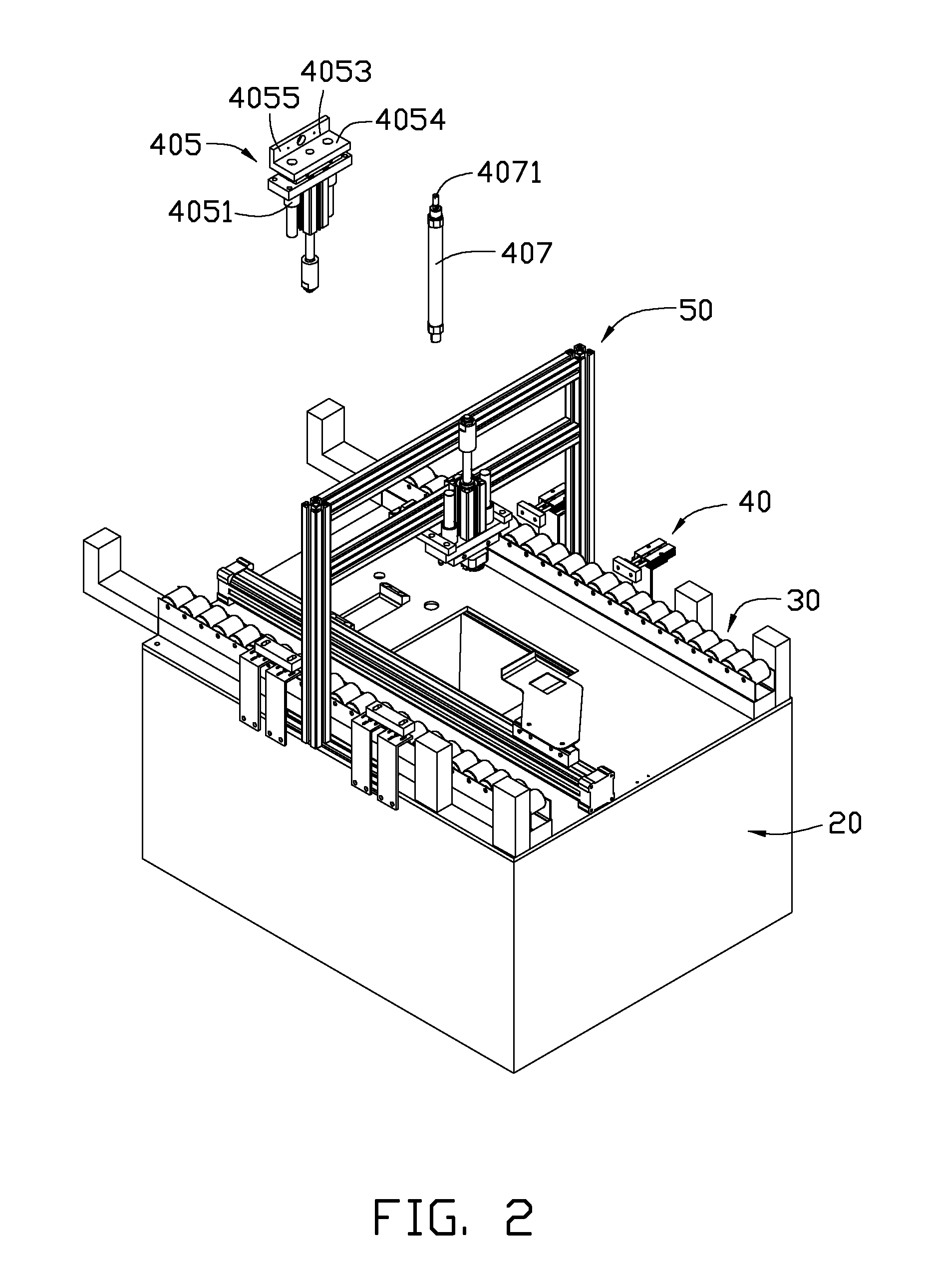
[0011]FIGS. 1 through 3 show an embodiment of a punch device 100. The punch device 100 includes a mounting platform 20, a feeding mechanism 30, a positioning and ejecting mechanism 40, and a punch mechanism 50. The punch mechanism 50 is mounted over the mounting platform 20 and is driven to move in a vertically linear manner, for punching a pre-punched workpiece 60 (the workpiece that is shown in FIG. 3 is one punched workpiece). The feeding mechanism 30 is mounted on the mounting platform 20, for conveying the pre-punched workpiece 60. The positioning and ejecting mechanism 40 is mounted on the mounting platform 20 and positioned adjacent to a specified position under the punch mechanism 50. The positioning and ejecting mechanism 40 positions the pre-punched workpiece 60 during a punching process, and ejects the punched workpiece 60 after the punching process, thereby facilitating an operator to take away the punched workpiece 60.

[0012]The mounting platform 20 includes a mounting p...


PUM

PropertyMeasurementUnit
angleaaaaaaaaaa
angleaaaaaaaaaa

Abstract

A punch device includes a mounting platform, a punch mechanism, a feeding mechanism, and a positioning and ejecting mechanism. The punch mechanism is mounted over the mounting platform for punching a pre-punched workpiece positioned on the mounting platform. The feeding mechanism is mounted on the mounting platform for conveying the pre-punched workpiece. The positioning and ejecting mechanism is mounted on the mounting platform and positioned under the punch mechanism, for positioning the pre-punched workpiece during a punching process, and ejecting the punched workpiece after the punching process is performed, thereby facilitating an operator to take away the punched workpiece.

Description

BACKGROUND[0001]1. Technical Field[0002]The present disclosure generally relates to a punch device or punch press.[0003]2. Description of Related Art[0004]Punch devices or presses are well known in the prior art for forming and cutting metal work pieces. A commonly used punch press or device generally comprises a die set. The die set includes a male punch and a female die. At the beginning of the punching process, the male punch is temporarily affixed to the end of a ram to move in a vertically linear manner The female die is positioned in a table or work bed. A work piece is positioned between the male punch and the female die. To initiate the punching sequence, the ram is moved downward, causing the male punch to enter the work piece and push it through the female die. This creates a desired hole or deformity in the work piece at a pre-determined and specified site, which usually is at the center of the work piece.[0005]However, after the punching process, the punched work pieces ...

Claims


Application Information

Patent Timeline
Patent Type & Authority Applications(United States)
IPC IPC(8): B26D7/32B21D45/02
CPCB21D28/265B21D45/003B21D43/26B21D43/023Y10T83/2092
Inventor TANG, YOU-LONGSUN, CHENG-FENGZHANG, DONG-PINGYANG, GUANG
Owner FU TAI HUA IND SHENZHEN
Why Eureka
Try Eureka