Ignition control apparatus

Active Publication Date: 2013-04-18
MITSUBISHI ELECTRIC CORP
View PDF0 Cites 7 Cited by
  • Summary
  • Abstract
  • Description
  • Claims
  • Application Information

AI Technical Summary

Benefits of technology

[0010]The present invention has been implemented in order to solve the foregoing problems in a conventional ignition apparatus; the objective the

Problems solved by technology

However, in the stratified-lean-combustion operation of an internal combustion engine, the distribution of inflammable fuel-air mixtures may vary in the combustion chamber of the internal combustion engine; therefore, there exists a problem that the ignition plug is liable to smolder.
In particular, in spray-guide-type stratified-lean-combustion operation where an unburned fuel is directly sprayed toward an ignition plug, smolder of the ignition plug occurs conspicuously.
As a result, there is posed a defect that, for example, the output decreases because the actual ignition timing is delayed.
As a result, there has been a problem that because ignition of the inflammable

Method used


Image

  • Ignition control apparatus
  • Ignition control apparatus
  • Ignition control apparatus

Examples


embodiment 1

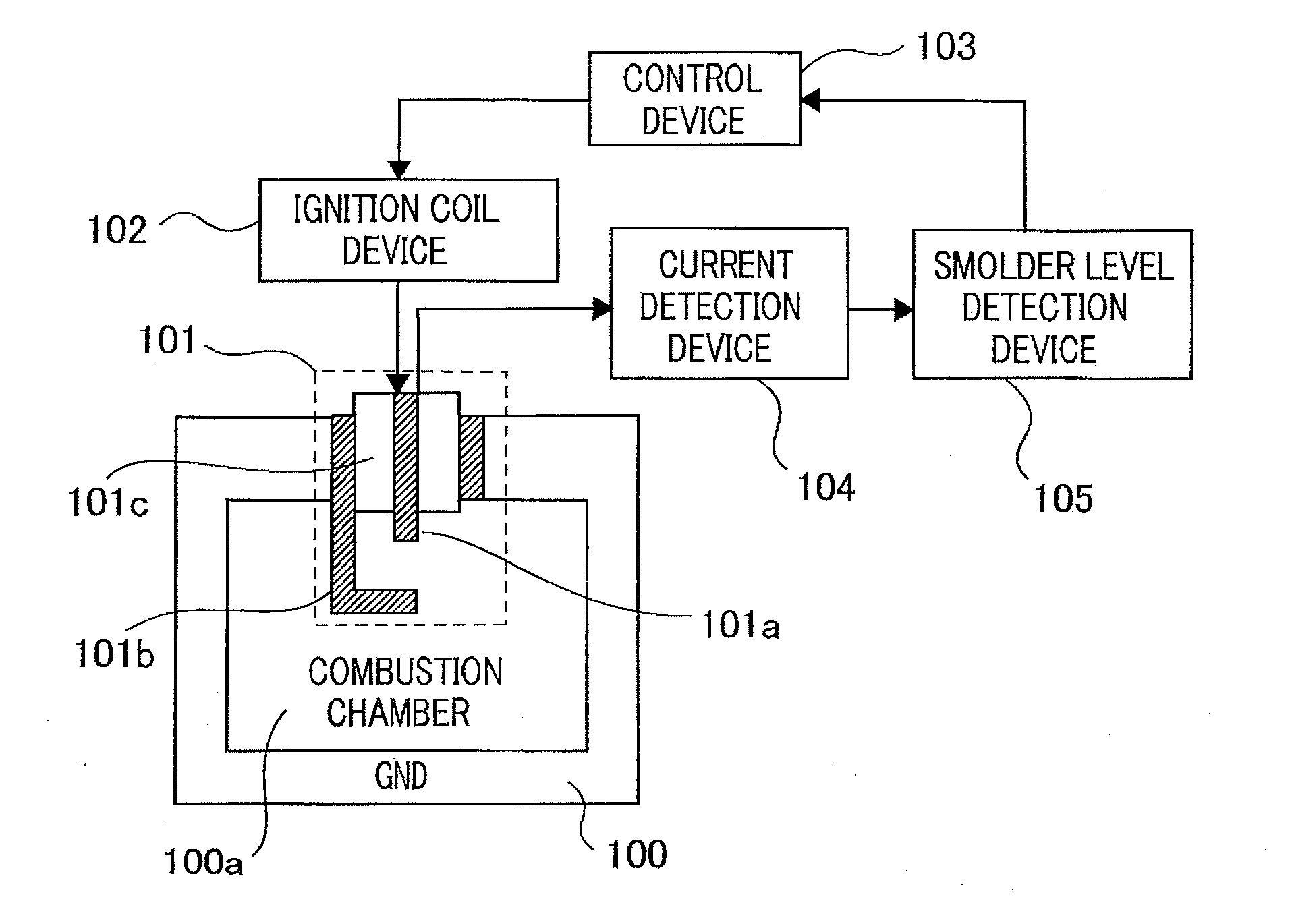
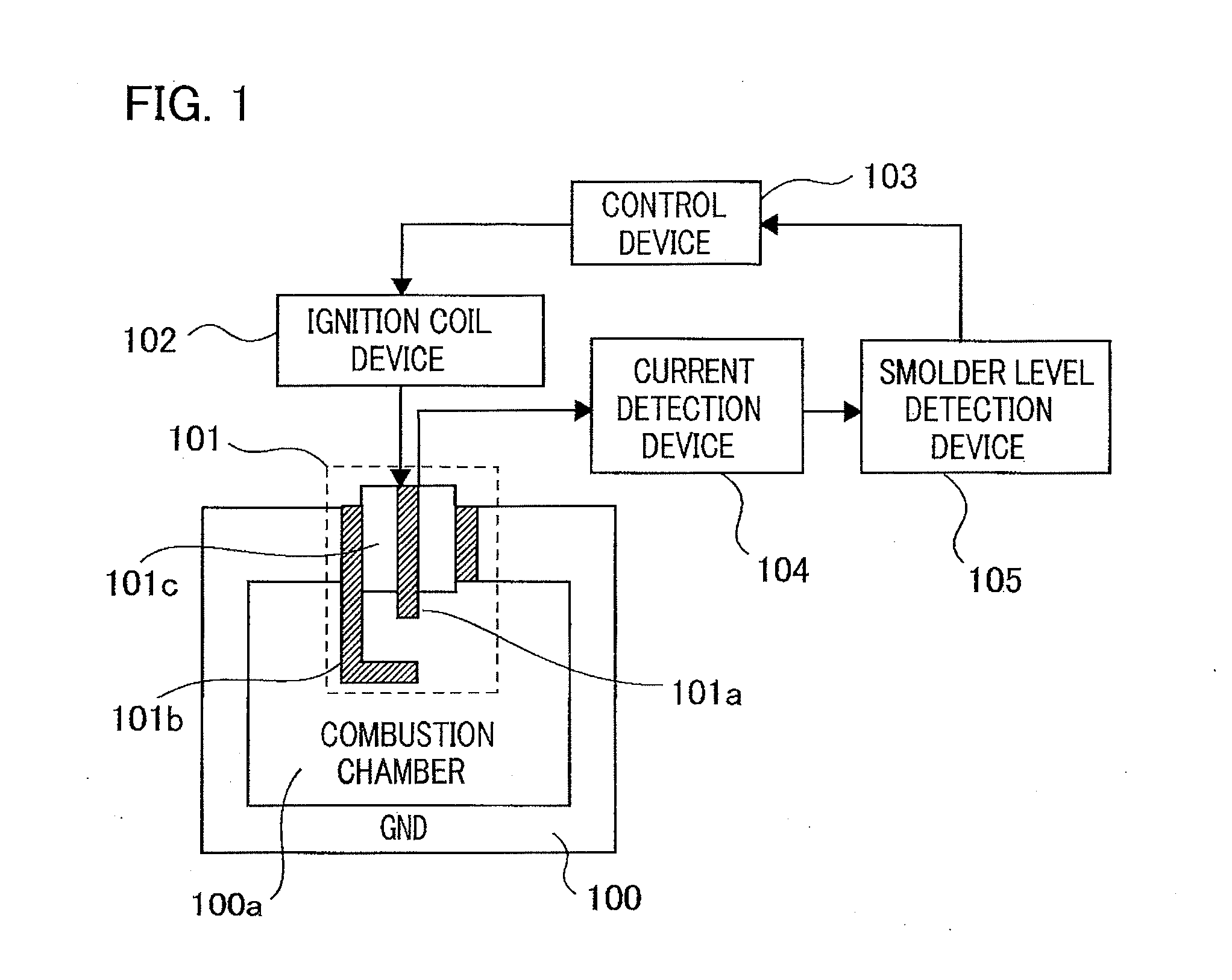
[0019]FIG. 1 is a configuration diagram illustrating an ignition control apparatus according to Embodiment 1 of the present invention. In FIG. 1, an ignition plug 101 mounted in an internal combustion engine 100 is provided with a central electrode 101a as a first electrode to which a high voltage is applied and a GND electrode 101b as a second electrode electrically connected with a cylinder block, which is a GND-level portion of the internal combustion engine 100. The ignition plug 101 is disposed in such a way that the central electrode 101a and the GND electrode 101b are exposed inside a combustion chamber 100a of the internal combustion engine 100; a predetermined high voltage for ignition is applied to the central electrode 101a and hence a spark discharge is produced in a gap between the central electrode 101a and the GND electrode 101b, so that an inflammable fuel-air mixture in the combustion chamber 100a is ignited and burned. The central electrode 101a and the GND electro...


PUM


Abstract

Ignition is performed in such a way that a bias voltage is applied to a first electrode of an ignition plug and a current detection device detects a current that flows in the first electrode, that based on the value of the detected current, a smolder level detection device detects the level of a smolder produced in the ignition plug, and that a control device controls, based on the detected smolder level, at least one of the timing of ignition, the number of ignition events per power stroke of an internal combustion engine, and the amount of energy accumulated in an ignition coil device.

Description


Claims


Application Information

Patent Timeline
Owner MITSUBISHI ELECTRIC CORP
Why Eureka
Try Eureka