Connection structure of braided wire

a technology of connecting structure and braided wire, which is applied in the direction of cable junction, cable termination, coupling device connection, etc., can solve the problems of increasing the number of assembly processes and leakage of noise to the outside, and achieves the reduction of parts and assembly processes, easy assembly, and improved shielding ability

Inactive Publication Date: 2013-04-18
YAZAKI CORP
View PDF17 Cites 13 Cited by
  • Summary
  • Abstract
  • Description
  • Claims
  • Application Information

AI Technical Summary

Benefits of technology

[0027]As described above, according to the ground structure of a braided wire having the configuration of the above (1), the terminal of the braid is put on the outer side of the cylindrical part provided to the device case, so that the braid and the device case are shield-connected. Thus, it is possible to omit a shield shell, thereby reducing the number of parts and the number of assembling processes. Also, the braid is directly put on the device case, so that the gaps between the shield shell and the connector and between the shield shell and the case are removed, contrary to the related art. Hence, the shield capability is improved.
[0028]According to the ground structure of a braided wire having the configuration of the above (2), the ring-shaped elastic seal is provided between the outer side of the fitting part provided to the housing of the connector and the inner side of the cylindrical part. Hence, it is possible to omit a surface seal and to secure the waterproof and oilproof capabilities by using the using the ring-shaped elastic seal that can be easily attached.
[0029]According to the ground structure of a br

Problems solved by technology

The braided wire has a covered electric wire and a cylindrical braid covering the covered electric wire and grounds the braid, so that noise leaked to the outside from the covered electric wire or noise originating from the outside

Method used


Image

  • Connection structure of braided wire
  • Connection structure of braided wire
  • Connection structure of braided wire

Examples


Embodiment Construction

First Illustrative Embodiment

[0048]Hereinafter, a ground structure 1 of a braided wire according to a first illustrative embodiment of the invention will be described with reference to FIGS. 1 to 8B.

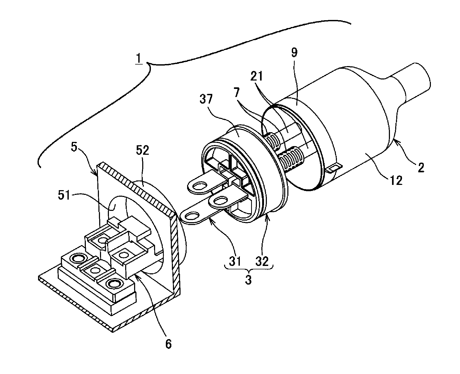
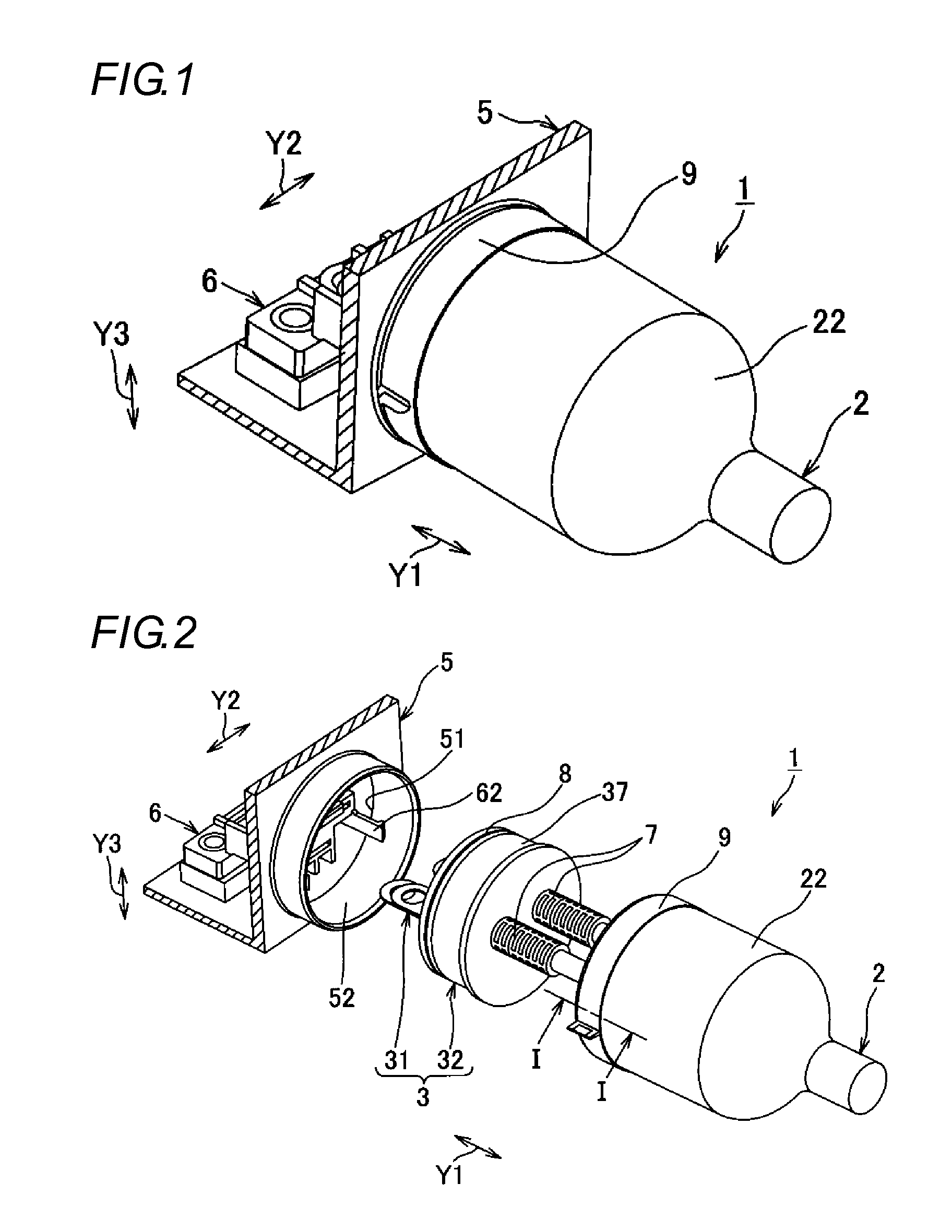
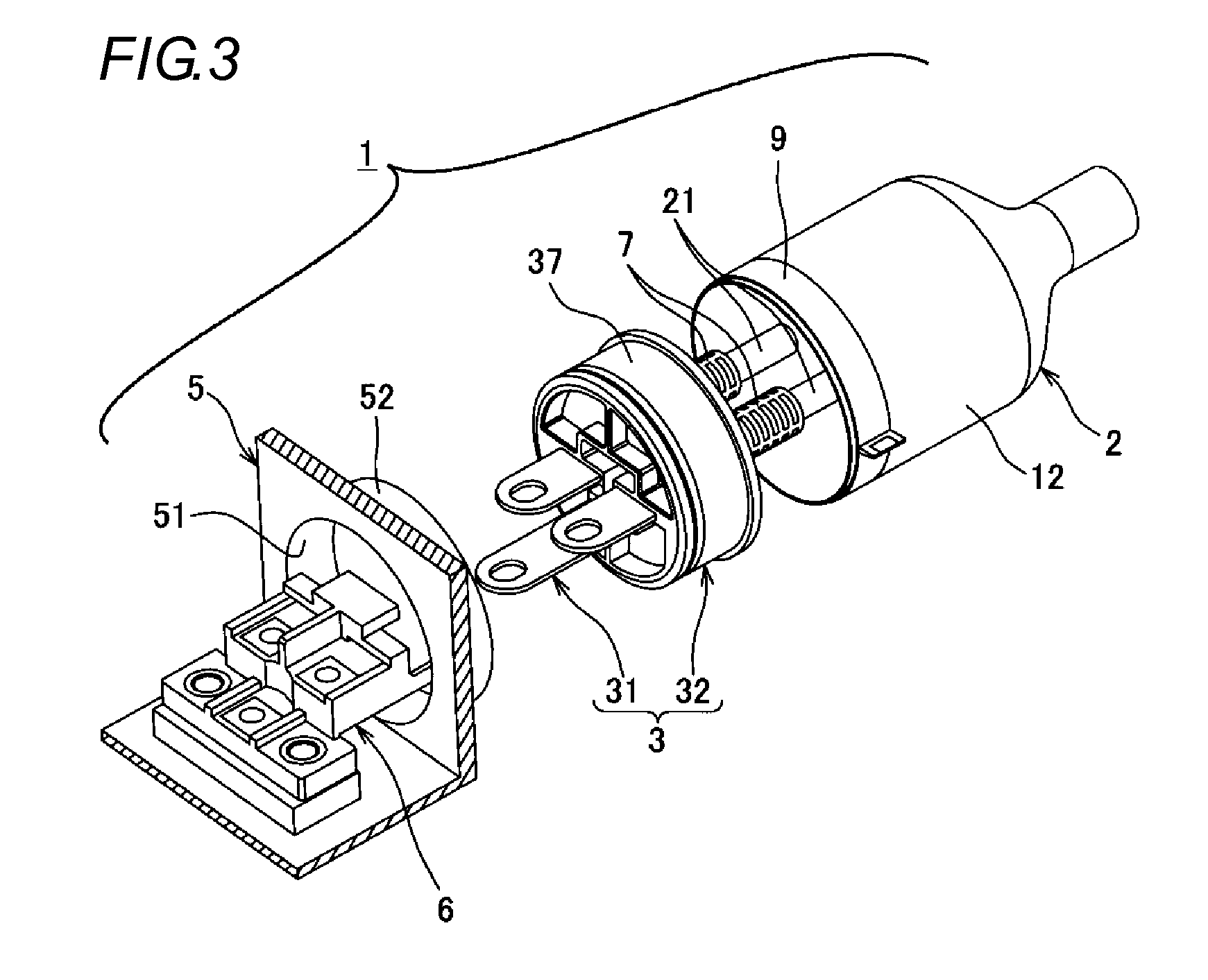
[0049]As shown in FIGS. 2 and 3, a ground structure 1 of a braided wire according to this illustrative embodiment includes a braided wire 2 having three covered electric wires 21 (refer to FIG. 4) and a cylindrical braid 22 collectively covering the covered electric wires 21 as a whole, a connector 3 that is attached to terminals of the covered electric wires 21, a device case 5 that has an insertion hole 51 for inserting the connector 3 therein, and a terminal block 6 that is fixed in the device case 5.

[0050]The covered electric wire 21 has a conductive core and an insulating covering part, which are not shown. The core (not shown) is formed by twisting one or more conductive wires. The covering part covers the core and is made of a synthetic resin such as polyvinyl chloride, for exampl...


PUM


Abstract

There is provided a ground structure of a braided wire having reduced the number of parts and the number of assembling processes and having improved a shield capability. A cylindrical part that is made to stand upright from a periphery of an insertion hole toward an outside of a device case is provided to the device case. A terminal of a 5 braid is put on an outer side of the cylindrical part of the device case and a shield band is wound on an outer side of the braid put on the outer side of the cylindrical part.

Description

DESCRIPTION[0001]1. Technical Field[0002]The invention relates to a connection structure of a braided wire, and more particularly, to a connection structure of a braided wire having a braided wire consisting of a covered electric wire and a cylindrical braid covering the covered electric wire and a device case having an insertion hole for inserting a connector attached to a terminal of the covered electric wire where the braid is connected to the device case.[0003]2. Background Art[0004]In a vehicle that is a moving object, electric wires are aligned so as to feed power from a power supply such as battery to devices such as various lamps and motors mounted on the vehicle and to transmit a control signal from a control device. Regarding the electric wires aligned in the vehicle, it has been known that braided wires are used due to measures against noise.[0005]The braided wire has a covered electric wire and a cylindrical braid covering the covered electric wire and grounds the braid,...

Claims


Application Information

Patent Timeline
IPC IPC(8): H01B5/12
CPCH01R13/6592H01R13/743H01R13/6273H01R2105/00H01R9/032H01B5/12H01R13/6596H01R13/65912
Inventor TANAKA, MASAHIROKATO, HAJIME
Owner YAZAKI CORP
Why Eureka
Try Eureka