Backlight control unit and display device using same and backlight control method

a control unit and display device technology, applied in the field of backlight control units and display devices using backlights, can solve the problems of black image waste or power to the lamps below the bars

Inactive Publication Date: 2013-04-18
HONG FU JIN PRECISION IND (SHENZHEN) CO LTD +1
View PDF5 Cites 5 Cited by
  • Summary
  • Abstract
  • Description
  • Claims
  • Application Information

AI Technical Summary

Problems solved by technology

Accordingly, power to the lamps belo

Method used


Image

  • Backlight control unit and display device using same and backlight control method
  • Backlight control unit and display device using same and backlight control method
  • Backlight control unit and display device using same and backlight control method

Examples


Embodiment Construction

[0010]Reference will be made to the drawings to describe specific exemplary embodiments of the present disclosure.

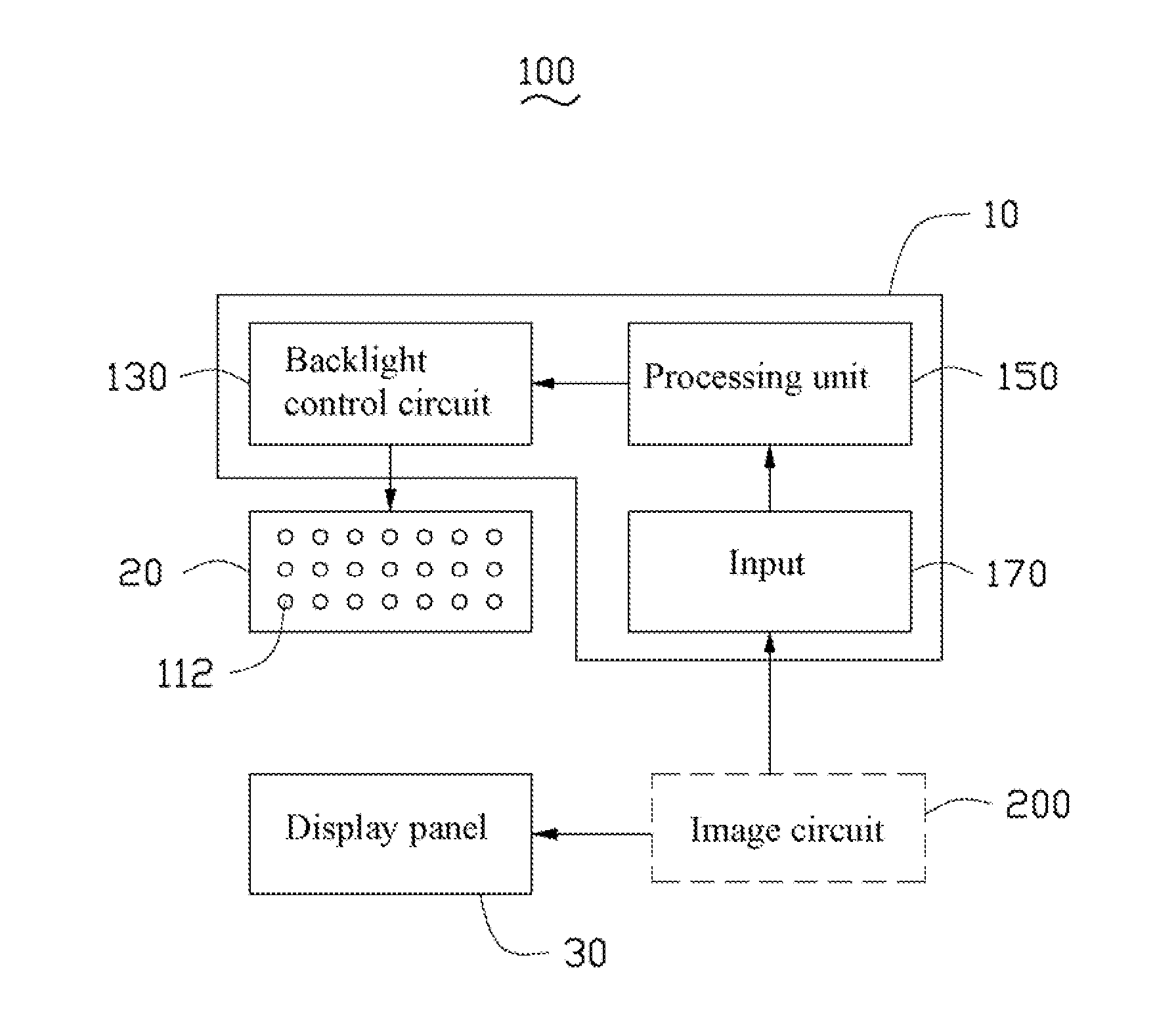
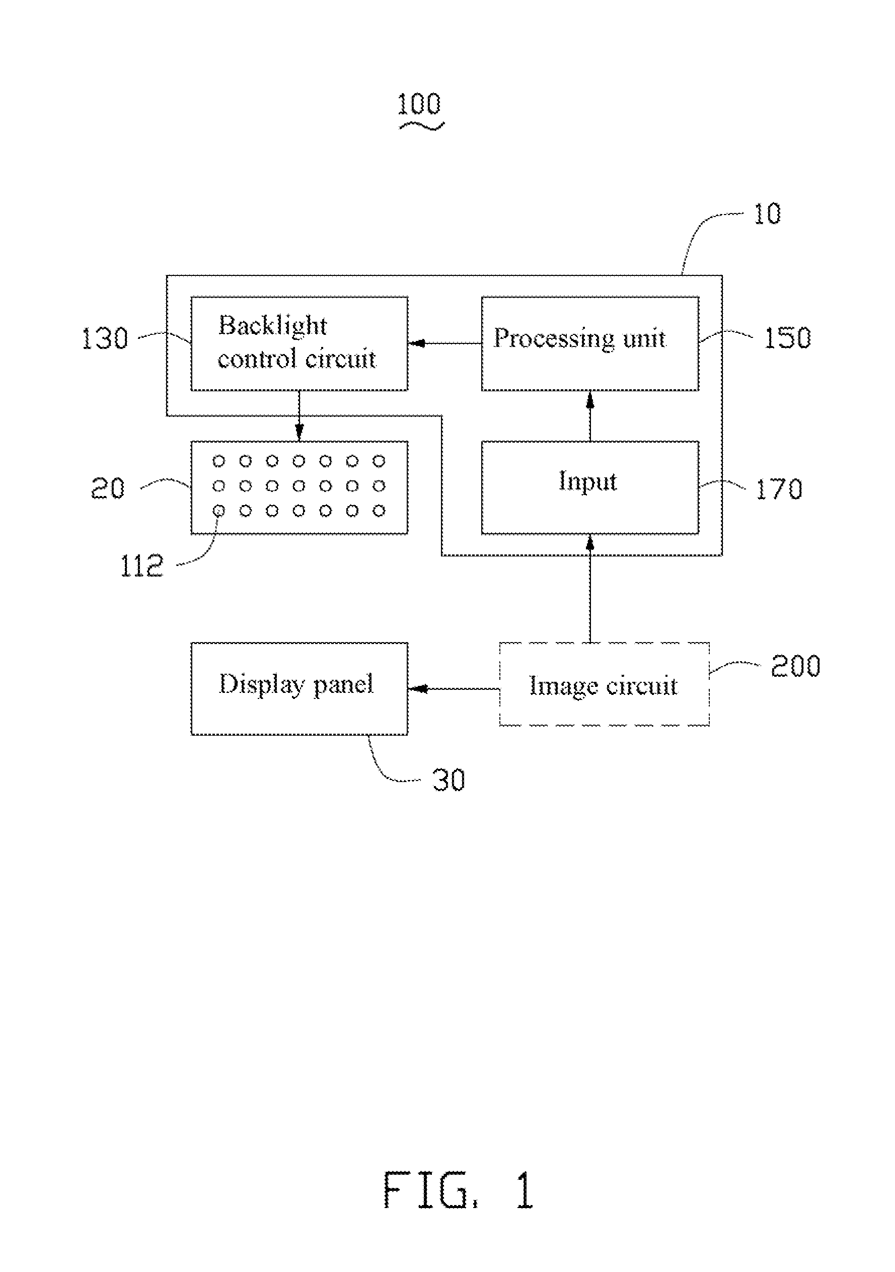
[0011]FIG. 1 is a block diagram of one embodiment of a display device 100. The display device 100 may be a liquid crystal display device, for example. The display device 100 includes a backlight control unit 10, a backlight module 20, and a display panel 30. The display panel 30 includes two opposite surfaces, a display surface and a back surface. The backlight module 20 is disposed adjacent and opposite to the back surface of the display panel 30, and provides light to the display panel 30 for displaying images. The backlight module 20 includes a plurality of lamps 112. The lamps 112 may be light emitting diodes, for example. The display panel 30 receives pixel data from an image circuit 200.

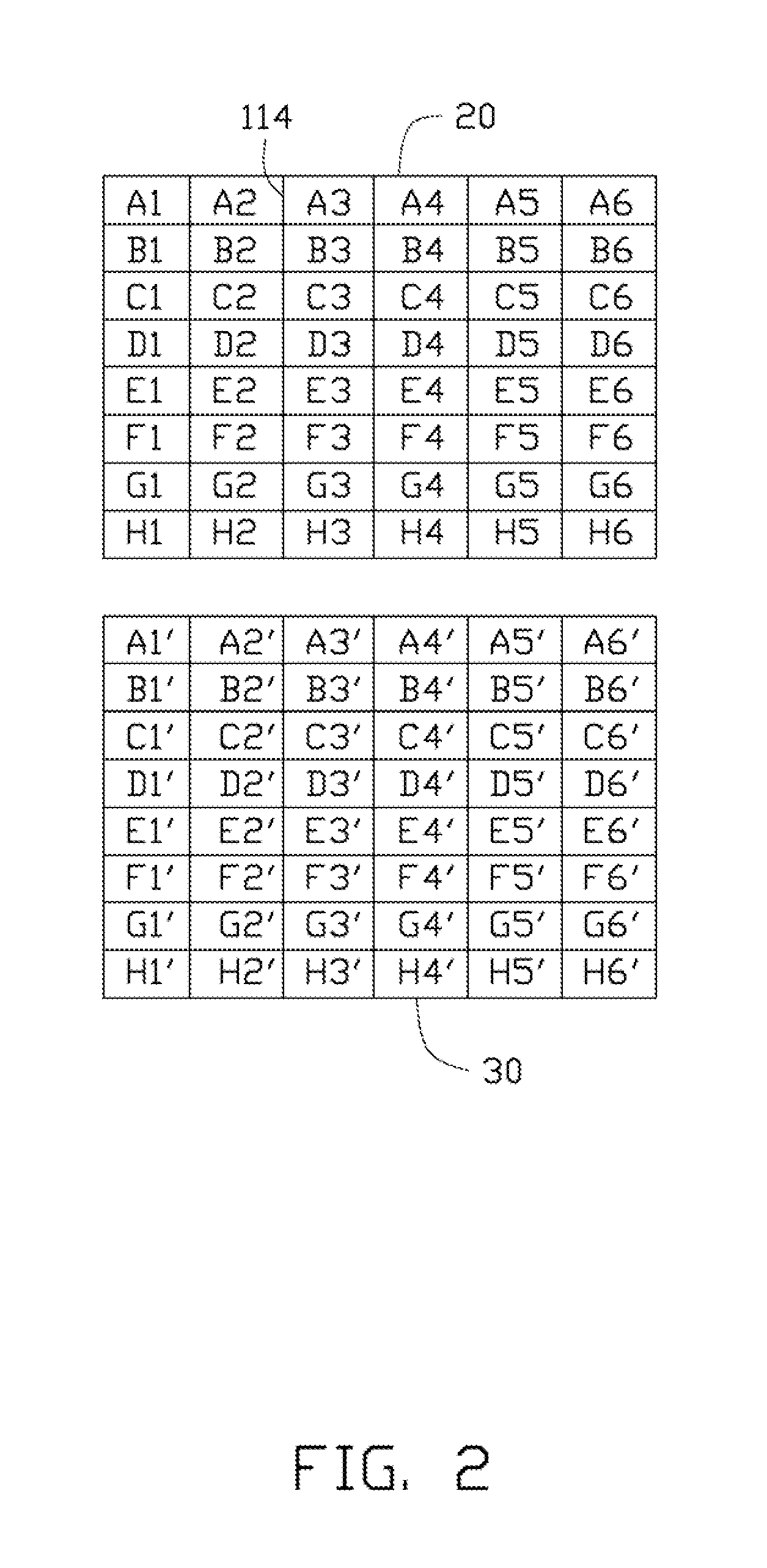
[0012]FIG. 2 is a view of a plurality of display regions A1′-A6′, B1′-B6′, C1′-C6′, D1′-D6′, E1′-E6′, F1′-F6′, G1′-G6′ and H1′-H6′ of the display panel 30 that are controlled by the...


PUM


Abstract

A backlight control unit for a display device includes a processing unit and a backlight control circuit. The display device includes a plurality of lamps and defines a plurality of display regions each display region being illuminated by at least one lamp. When the processing unit determines that one or more display regions on the display device are constantly displaying a black image, the processing unit outputs a control signal to the backlight control circuit. The backlight control circuit turns off the lamps serving the one or more display regions displaying the black image, based on the control signal.

Description

BACKGROUND[0001]1. Technical Field[0002]The present disclosure relates to a backlight control unit, a display device using the backlight control unit and a backlight control method thereof.[0003]2. Description of Related Art[0004]A liquid crystal display device generally includes a panel for displaying images, a backlight module for providing light to the panel, and a backlight control unit for controlling the backlight module. When the display device is displaying images, the lamps of the backlight module are all turned on by the backlight control unit. However, images may be only displayed on a portion of the display device, and the other portions of the display device may display a black image or no image. For example, when the display device is displaying a film, the display device displays dynamic images of the film on a central region of the display panel, and displays bars or a black image on a periphery of the display panel. Accordingly, power to the lamps below the bars or ...

Claims


Application Information

Patent Timeline
IPC IPC(8): G09G5/10
CPCG09G3/3426G09G2360/16G09G2320/0626
Inventor GUO, XIN
Owner HONG FU JIN PRECISION IND (SHENZHEN) CO LTD
Why Eureka
Try Eureka