Tunable filter using a wave plate

a wave plate and filter technology, applied in the field of tunable filter, can solve the problem of complex prior art configuration of these systems, and achieve the effect of eliminating polarization splitting and recombining elements, and low polarization dependent losses

Inactive Publication Date: 2013-04-18
OPTOPLEX CORP
View PDF2 Cites 3 Cited by
  • Summary
  • Abstract
  • Description
  • Claims
  • Application Information

AI Technical Summary

Benefits of technology

[0010]It is another object of the present invention to provide tunable filters that have low polarization dependent losses.
[0011]Another object of the present invention is to provide tunable filters that eliminate polarization splitting and recombining elements.
[0012]An object of the present invention is to provide tunable filters that are compact.

Problems solved by technology

Unfortunately, prior art configurations for these systems are complicated.

Method used


Image

  • Tunable filter using a wave plate
  • Tunable filter using a wave plate
  • Tunable filter using a wave plate

Examples


Embodiment Construction

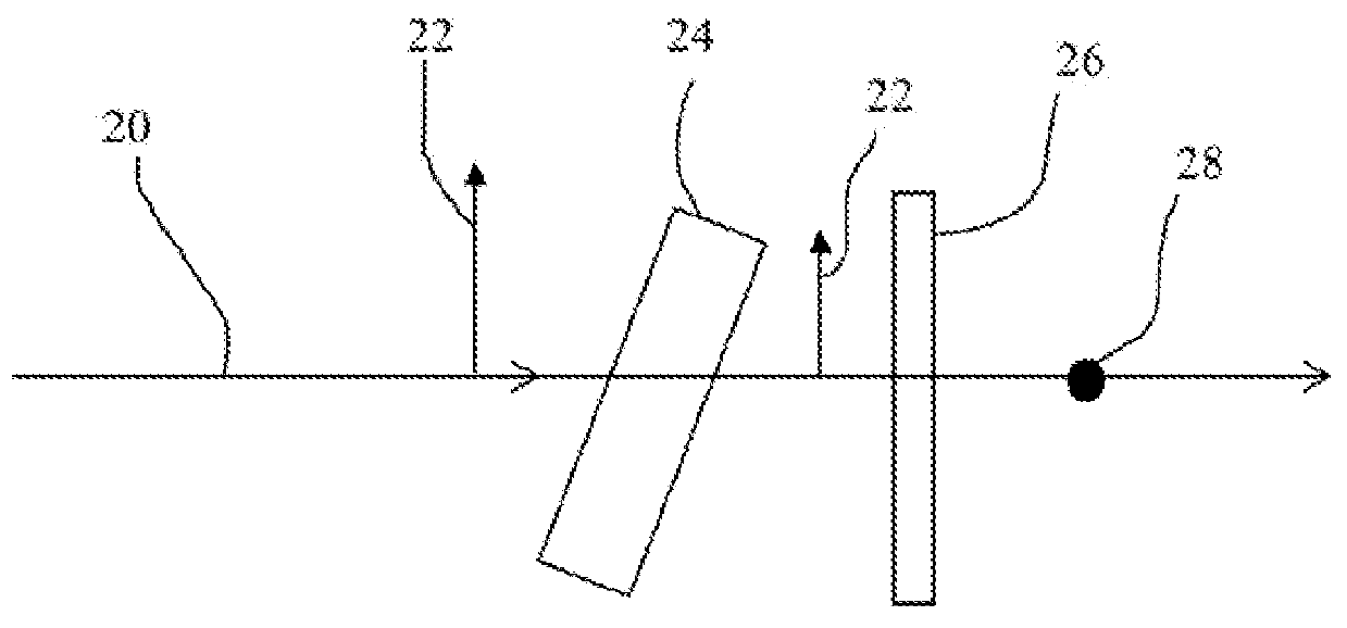
[0028]When a linearly polarized beam passes through a wave plate whose polarization axis is at an angle α with respect to the direction of polarization of the beam, the polarization direction of the beam is rotated by an angle 2α. For example, when α=45 degrees, a linearly polarized beam with its polarization direction in the vertical direction (X-axis) becomes a linearly polarized beam with its polarization direction in the horizontal direction (Y-axis). Referring specifically to FIG. 2, an input beam 20 that is P-polarized, as shown at reference number 22 passes through interference filter 24 and remains P polarized. After passing through ½ wave plate 26, beam 20 is rotated 90 degrees and then has the S-polarization orientation, as shown at reference number 28, relative to the interference filter.

[0029]FIG. 3 shows an embodiment of the invention in which a quarter wave plate is inserted between a tilted interference filter and a mirror. The quarter wave plate is oriented such that...


PUM


Abstract

Tunable filters are provided that have transmittances that are independent of the polarization state of an incident beam. The tunable filters include an interference bandpass filter positioned to transmit an input beam of light to produce transmitted light. A wave plate is positioned to rotate the polarization of the transmitted light and a reflector is positioned to reflect the rotated light so that it propagates through the wave plate a second time and then passes through the interference filter a second time to produce second transmitted light.

Description

CROSS-REFERENCE TO RELATED APPLICATIONS[0001]This application claims the benefit of U.S. Provisional Patent Application No. 61 / 540,867 titled “Tunable Filter Using a Wave Plate,” filed Sep. 29, 2011, incorporated herein by reference.BACKGROUND OF THE INVENTION[0002]1. Field of the Invention[0003]The present invention relates to tunable interference filters, and more specifically, it relates to tunable filters that have a transmittance that is independent of the polarization state of the incident beam.[0004]2. Description of Related Art[0005]The transmission profile of an interference bandpass filter comprises the transmission peak wavelength, the transmittance and the pass bandwidth. The transmission peak wavelength is a function of the angle of incidence of incoming light. Increasing the incident angle will shift the transmission peak wavelength to a shorter wavelength. Typically, the amount of shift depends on the polarization state of the incident light. Any polarization state ca...

Claims


Application Information

Patent Timeline
Patent Type & Authority Applications(United States)
IPC IPC(8): G02B5/28
CPCG02B5/28
Inventor SONG, DARYUANHSIEH, YUNG-CHIEH
Owner OPTOPLEX CORP
Why Eureka
Try Eureka