Combination optics light emitting diode landing light

a diode landing light and combination optics technology, applied in the field of light modules, can solve the problems of significant longer life and achieve the effect of constant thickness

Active Publication Date: 2013-04-18
OSRAM SYLVANIA INC
View PDF0 Cites 39 Cited by
  • Summary
  • Abstract
  • Description
  • Claims
  • Application Information

AI Technical Summary

Benefits of technology

[0006]An embodiment is a light module. An LED array is centered around a horizontal longitudinal axis. The LED array emits light in an angular distribution centered around the longitudinal axis. A lens is disposed longitudinally adjacent to the LED array for receiving light emitted by the LED array. The lens has a thickness that is a maximum at the longitudinal axis and decreases monotonically away from the longitudinal axis. A reflecting surface extends generally from the LED array toward the lens. Proximate the LED array, the reflecting surface has a lateral diameter generally equal to a lateral outer diameter of the lens. The reflecting surface has a base curvature that is a paraboloid centered about the longitudinal axis and has a focus disposed at a center of the LED array. The reflecting surface includes a plurality of facets superimposed on the base curvature. The facets reflect light into a distribution proximate the longitudinal axis and includes light that is directed farther away from the longitudinal axis in both lateral directions and downward. The lens is supported by a generally transparent cover. The cover includes a peripheral portion that laterally circumferentially surrounds the lens and has a generally constant thickness throughout. The peripheral portion and the lens are both integral to the cover.

Problems solved by technology

When compared with conventional incandescent bulb-based systems, the LED systems may be smaller, may have significantly longer lifetimes, may require significantly less electrical power for operation, and may provide additional illumination in visible regions other than the “hot spot” directly in front of the airplane.

Method used


Image

  • Combination optics light emitting diode landing light
  • Combination optics light emitting diode landing light
  • Combination optics light emitting diode landing light

Examples


Embodiment Construction

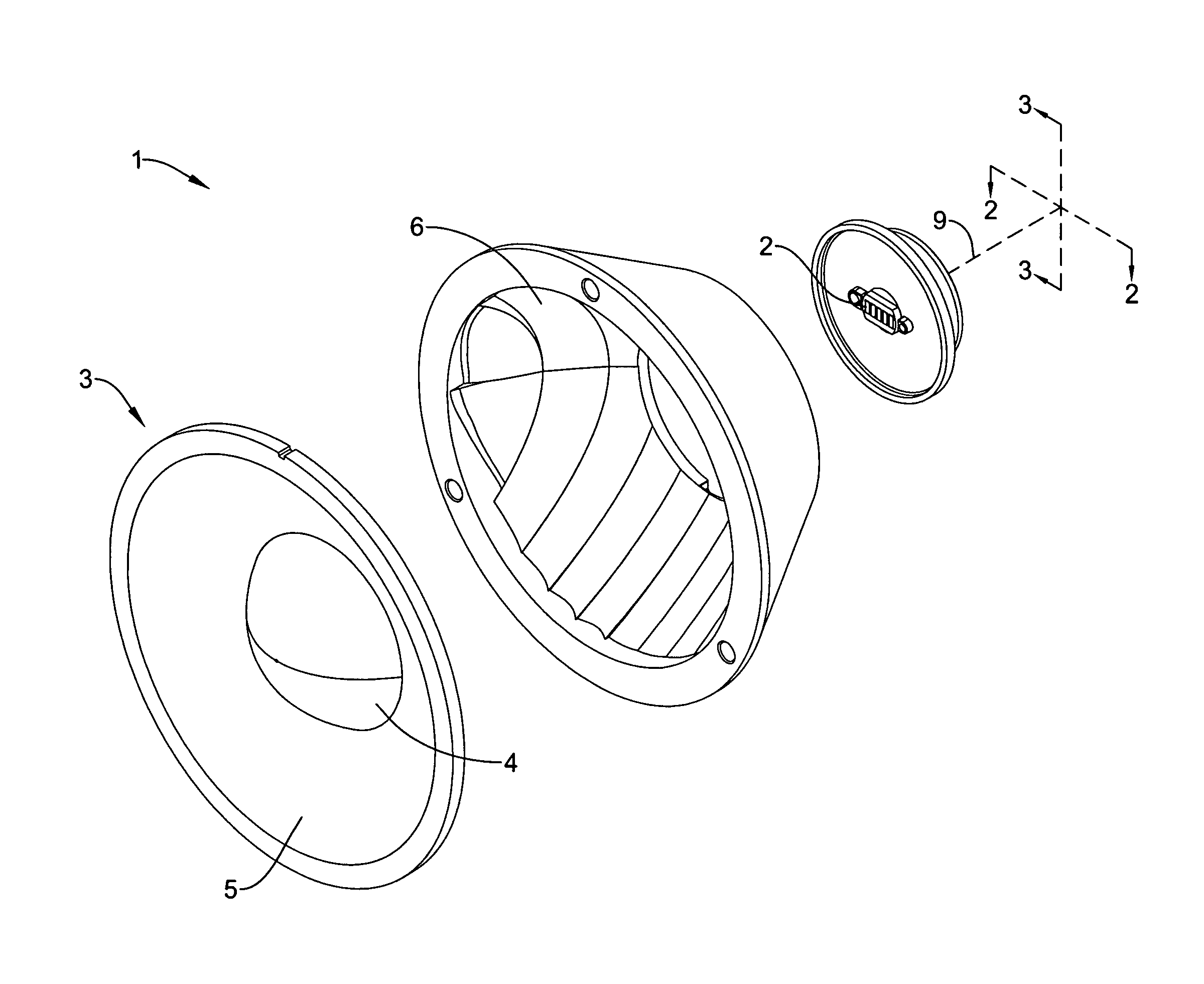
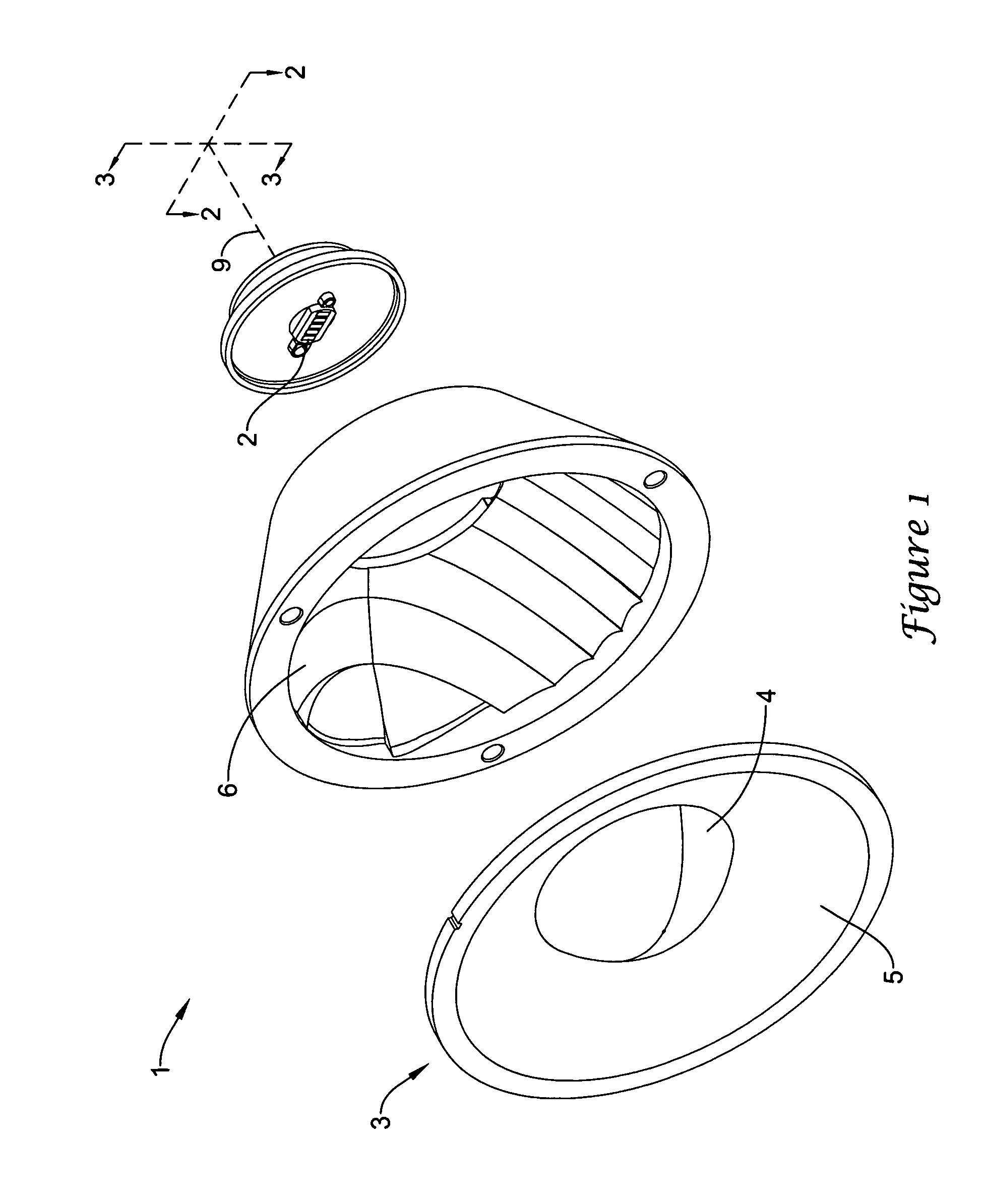
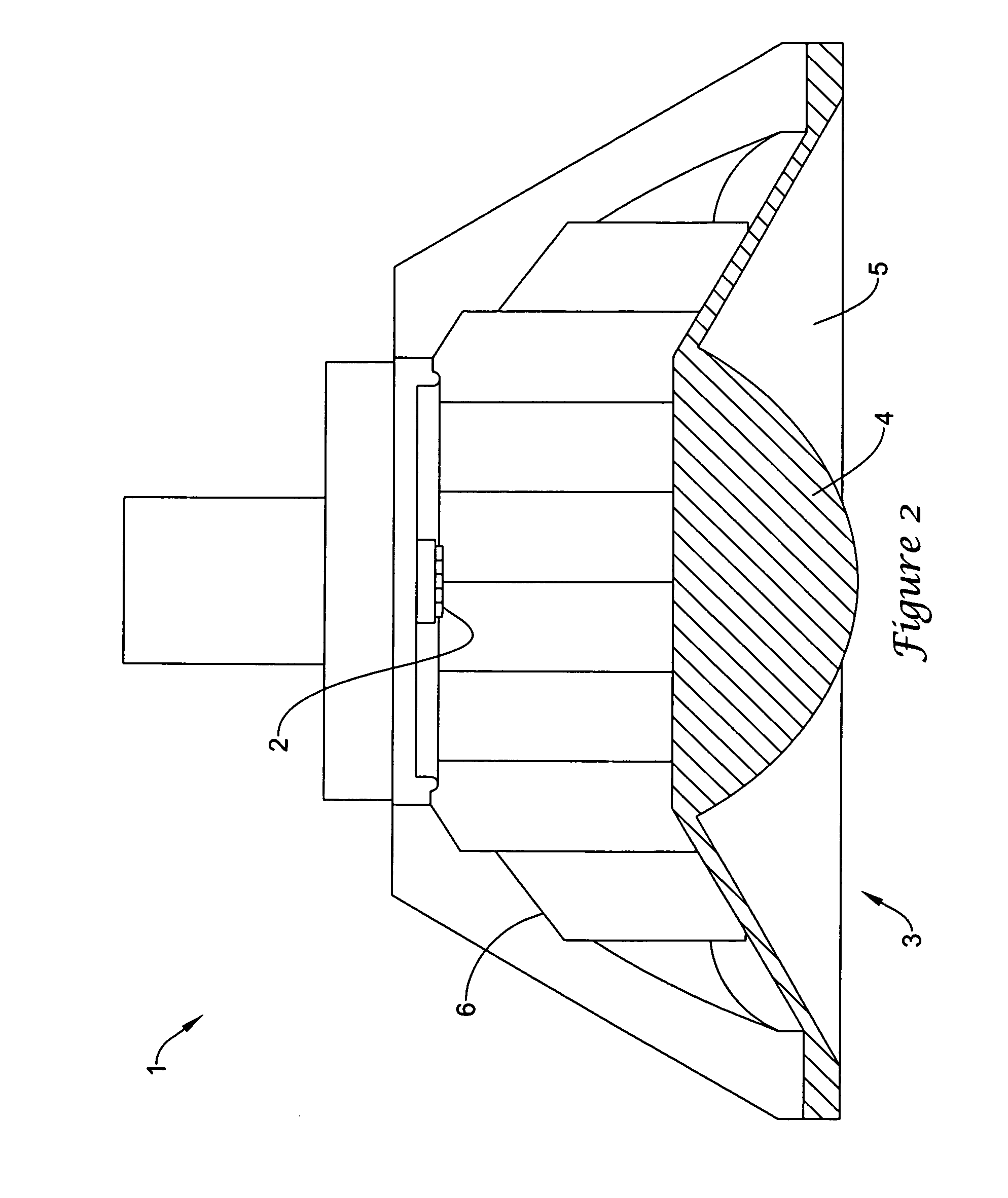
[0016]In this document, the directional terms “up”, “down”, “top”, “bottom”, “side”, “lateral”, “longitudinal” and the like are used to describe the absolute and relative orientations of particular elements. For these descriptions, it is assumed that the light module is for a landing light mounted on the front of an airplane, with an output beam that is directly generally horizontally in front of the airplane. Although there may be some slight inclinations away from true horizontal during use, for the purposes of this document, it will be assumed that a longitudinal axis of the landing light is denoted as being horizontal. It will be understood that while such descriptions provide orientations that occur in typical use, other orientations are certainly possible. The noted descriptive terms, as used herein, still apply to the landing light, even if the landing light has an orientation other than installed in the front of an airplane, or is uninstalled in its typical orientation. In o...


PUM


Abstract

A light module (1) suitable for use as a landing light for an airplane is disclosed, using an elongated array (2) of light emitting diodes (LEDs) as the light source. Light from the LEDs is directed toward a transparent cover (3). The cover (3) may include a plano-convex lens (4) at its center for nominally collimating the light from the LEDs. The cover (3) may also include a generally featureless peripheral region laterally circumferentially surrounding the lens (4). A faceted reflecting surface (6) having a generally parabolic base curvature (8) may extend circumferentially around a longitudinal axis of the landing light from the LEDs to the cover (3). Light exiting the LEDs at a relatively high angle of exitance reflects off the faceted reflecting surface (6) and transmits through the generally featureless peripheral region of the cover (3).

Description

TECHNICAL FIELD[0001]The present invention relates to a light module using light emitting diodes as the light source, and a combination of reflective and refractive optics to produce the desired light output pattern.BACKGROUND OF THE INVENTION[0002]Aircraft landing lights are primarily intended to illuminate the runway directly ahead of the aircraft, with a secondary function of making the aircraft visible to other aircraft. For smaller airplanes, there may be a single landing light mounted near a lower portion of the front of the airplane. For larger aircraft, there may be multiple landing lights mounted on or near the underside of the airplane, typically near the front landing gear and the underside of the wings near the fuselage, although other locations may also be used. In general, landing lights should be extremely bright in an area or angular range directly in front of the aircraft (sometimes referred to as the “hot spot”), as well as require as little electrical power as pos...

Claims


Application Information

Patent Timeline
Patent Type & Authority Applications(United States)
IPC IPC(8): F21V5/04F21W107/30
CPCB60Q1/04B60Q1/20F21S48/1154F21S48/1258F21Y2101/02F21V13/04F21V5/048F21V7/048F21S48/1275F21Y2115/10F21S41/143F21S41/151F21S41/255F21S41/265
Inventor RICE, LAWRENCE M.
Owner OSRAM SYLVANIA INC
Why Eureka
Try Eureka